I posted the following picture in another thread here, and was asked about the method of making the bridge abutment. Rather than deviate from the intent of that thread, which I didn’t start, I’m posting here in response to the question. (click on the photos to enlarge)
The abutments and piers shown are all cast in patching plaster, using moulds made from styrene. I used a product from the Canada Gypsum Company called Durabond 90, a very strong and hard patching plaster that contains a catalyst, causing it to set in approximately 90 minutes. There are also other setting times available, denoted by the number following the name. I believe that U.S. Gypsum makes a similar product, although both Hydrocal or dental plaster will also work. I like this material because, no matter to what consistency you mix it, in about 90 minutes, it will set. Full drying can take several days, which gives you ample time to carve in rock or stone detail if desired. After that, it becomes very hard. I made moulds from .060" sheet styrene, taking into consideration the size (depth) of the bridges being used. Unfortunately, I don’t at present have a camera, so I’m unable to show you a picture of the mould. Most of the moulds are two-piece, each piece consisting of one end and one side, and are constructed so that they are upside-down when being filled. The moulds were held together with elastic bands during filling and drying. Vegetable oil, applied with a piece of paper towel before final assembly, was used as a mould release. I cut narrow strips (4’ or 5’ scale wide), then edge-glued these to the outside of the moulds, both to prevent the mould from bulging out when filled with plaster, and to assist in lining up the two halves of the mould. One half-mould includes the necessary shapes to form the top of the pier or abutment, which gives a nicely finished surface on which the bridge can rest.&nb
Wayne - I really like your work! Those are some great bridges. I particularly like the wide shallow river shot. Very impressive. I wouldn’t mind seeing some other parts of your layout. Based on your expert work on the bridges and abutments the rest of the layout would be worthy of a look see. Thanks for sharing your hard work and your techniques. Terry
Wayne. That’s by far the best simulated water i 've seen! Please share how you colored it. Those bridges are spectacular! Were they built from ME kits or scratched? I’ll be looking forward to more of your work.
Thanks to all for the warm reception. Bob, the “water” in all of the scenes is more Durabond, applied over a plywood riverbed. I misted a little “wet” water over the plywood first, then spread a fairly stiff batch of Durabond over it, using drywall knives to work the surface, to try to impart some motion to the water. The eddies around the bridge piers were done with a narrow blade, while the rapids, seen in the overhead shot, were raised by dabbing the surface of the wet plaster with a piece of sponge. After the Durabond had dried thoroughly, (it’s probably only about an eighth of an inch thick, but I left it for a couple of days), I used a 2" brush to apply latex house paint to the “water”. Near the shore, I used the same brown that I use as a base earth colour, while the deeper areas were done with the same dark grey/green that I use for background foliage. The second colour was applied while the first was still wet, allowing me to blend the colours together where they met. Any “white water” was added using white latex primer on a small brush. When that had dried, overnight, I applied three coats of water-based high gloss urethane, allowing the suggested time between coats.
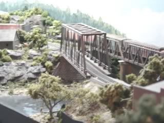
The bridges over the widest river consist of , from the first picture, an Atlas through girder, cut apart and rebuilt as a deck girder, the the Central Valley truss, followed by another rebuilt Atlas, then two M.E. fifty-footers, and then an M.E. thirty-footer. The two photos of the next bridge, including the overhead view, show a pair of Atlas deck trusses. Unseen, to the left, and beneath the loco’s tender in the overhead view, is a 30’ Micro Engineering deck girder. In the photo showing an overall view of the two bridges, the high bridge in the background is from M.E., while the lower structure is compose fo, from left-to-right, two M.E. 30’ deck girders, two Atlas deck trusses, and another reworked Atlas through girder. The final two shot
Thanks for posting about the bridge piers…very helpful. Styrene for molds…hmmm that is a great idea. Next time you make one, take some pics… us noobs would love to learn. Just starting to scratchbuild.
As for the bridges… WOW. WOW. Anyway, I love the last 2… I think I will look for an atlas deck girder to add to my 150’ ME bridge I was just about to start. Thanks again for posting… man, you set the bar high (reminds me of some of Bob’s work [;)]
Thanks for the kind words, guys. I haven’t actually been hiding, Terry, I come here fairly often, although I usually just add comments and the occasional photo to threads that I find interesting. There are quite a few more photos to be found through the links that I posted. Brian, I have most of those moulds, and when I get a new computer that’s capable of retrieving the pictures from my new camera, I’ll try to add a couple of photos. I agree: it’s much easier to show the mould than try to describe it. Cliff (great name for a guy who likes bridges[:D]), you have a very nice layout, and that arched bridge is really neat. Lots of locos, too. What scale are you in?
Please tell us about the very interesting rugged-looking gas-electric e.g prototyped or free-lanced, kit-based or scratch etc., Several other views would be nice too.
Ditto - Scuba…What a great layout, it needs to be published. [tup] Great work. The idea of casting and making bridge abutments out of scrap wood is a better choice and a cost saver over Chooch and other resin products.
Good to see you on this forum also. Your work is as always …outstanding!!! Geez man, I have to learn how to weather like you. Very nice bridge abutments.
Once again, thanks for the compliments and for taking the time to view the photographs. Isambard, the gas-electric doesn’t have a particular prototype, although it was inspired by photos of several prototypes, including those of ATSF and CNR. The carbody is a Rivarossi combine, with a couple of extra windows added in the passenger section. The part of the body shell with the baggage door was cut out and turned end-for-end, to place the door closer to the rear and a new baggage door was fabricated. This gave me enough room to add a 15’ postal compartment, with a scratchbuilt door and windows from an Athearn Pullman. The doors and windows in the front end were cut into the carbody and framed with strip styrene. The paraphenalia on the roof is from several sources: the air intake louvres at the front are scratchbuilt, with side outlets from an Athearn Geep. The radiator coils on the roof are from an MDC boxcab, and the roofwalks atop that are walkway gratings from a Tichy coaling tower. The fairing behind that is the ends of New England Rail Service’s a/c duct, with the rooftop torpedo air tanks and three transverse spark arrestors from Detail Associates. They also supplied the horns, upper and rear lights, and the carbody vents, while the bell and number boards are from Details West. The markers, headlight, and bracket are from Cal-Scale, and the pilot is from a Bachmann Santa Fe Northern. MV Products lenses were used. Grabirons are brass wire, and the stirrup steps are built-up from .010"x.030" brass barstock. The passenger compartment has a very basic interior featuring Pike Stuff coach seats, and an American Limited diaphram has been fittted to the rear door. I beefed-up the underframe a bit with some strip styrene, then added a UC brake system from PSC. The rear truck was modified with Athearn metal wheels and scratchbuilt wipers, so that it picks up current from both rail
Thanks for that great information Doc. Together with the photos, inspirational indeed! I’ve just found my way to “some foe-toes” and found your other photos-love the steam shots, particularly of massive 4100.
That is some of the best work I have seen in quite a while. You have obviously applied a lot of quality craftsmanship to those scenes. It is an inspiration to the rest of us. Has your layout been featured in any of the magazines. If not, it should be.
Isambard, the 4100, and most of the CNR locomotives belong to a good friend who visits often to take photos of his trains on my layout. We generally share the photo duties, and the resultant photos. I painted most of his locos, and have modified or rebuilt many of them. The only CNR loco in there that’s mine is the rebuilt Proto 0-8-0.
John, I submitted some photos and a brief outline of construction details of the gas-electric to RMC, but never got a reply (ssae was included). That was around the time of 9-11, although I don’t know if that had anything to do with it. Many years ago, these diesels, below, were featured in Paintshop, in the February, 1980 issue of Model Railroader. The novelty was that the lettering was done by using dry transfers as a painting “mask” for the lettering, as no one, at that time, made it in the proper colour. The actual paint job was done with custom-mixed PollyS, using a brush. The cab heralds, unavailable in either the proper size or colour, were done freehand, with a brush. Both models were later upgraded with the newer Athearn trucks (the 403 had the old metal sideframes, while 76 was a dummy). Both units have also been motored/remotored with Mashima can motors and have had quite a bit of extra weight added.
Most of the work that I do, be it remotoring locomotives, scratchbuild, kitbashing or even layout building just sort of “happens”, usually with some careful thought, and occasionally a sketch. Most of the constuction methods evolve as I work, and I often have to have the model in front of me, as I did with the gas car, in order to recall construction details. I’ve lately begun to try and document things as I work, as I did when rebuilding a quartet of Athearn Mikes, to increase their pulling power. However, I find this very distracting, as my preference is to just “work”, uninterrupted, for 10 or 12 hours
Sitting here looking at the steamer going across the river, I thought…, “if it goes over the edge it’s gonna be one wet locomotive”. That’s how credible your water is. In a lot of the pictures it was a bit hard to tell if it was the real thing or a model. The abuttments, the water… the trees… oh… are those super trees? They look top notch!
Thanks for posting these, I love seeing things like this!