I am in the process of doing a complete rewire of a 12’ x 3’ N scale DC layout and converting it to DCC at the same time. There are 15 Atlas electric turnouts, withh the associated “slide and press” buttons. I was looking to replace those buttons with momentary rocker switches, up flick, down, flick, auto return to center off. The problem I am haviing is that the turnouts have 3 wires (red green black). How would you wire these to the new buttons. they are DC so assuming Single pole, 3 pin switches may do the job, red top, black common, green bottom…but I have zero knowledge of how these switch motors function. I assume since they are DC, switching one way is the red, the other is the green, with black common return.
I can hear yall laughing already, but I am a complete noob to the nuances of how these function. Any help would be greatly appreciated.
No need for any laughing! An honest question deserves an honest answer.
As you already know the center screw on the Atlas switch machine is a ‘common’ terminal. The other two are the ‘switched’ wires to energize one coil or the other on the machine.
Your ‘other’ side of the circuit would go to the center terminal of the single-pole, double throw electrical switch.
If you sketch out the wiring you’ll have a better visual understanding of how it works.
There’s a little discussion about the Atlas switch machine wiring here:
when using a momentary SPDT center-off switch, one side of power (either + or -) is connected to the center terminal of the switch and the other side of power to the middle terminal on the switch motor. The end terminals on the switch are connected to the side terminals on the switch motor.
I do not like the Atlas switch system. It completely removes any analog brain-connection to the layout shape and thus is almost completely missing any intuitive connection. A schematic layout control panel is easily done with a thin piece of plywood and 1/4" wide tape to signify the layout pathways. Since it’s DCC and you don’t need Cab-selecting power switches for track sections, you only have to worry about the turnouts.
For Atlas track turnouts, I always used momentary push buttons, in combination with a capacitive discharge unit (via Peter J. Thorne’s “Practical Electronic Projects for Model Railroading”). It takes two momentary pushbuttons, but you have that if you make the schematic control panel, because each turnout diverges into two track sections, allowing you to put one pushbutton at the throat of each diverging track section. It’s much more intuitive if you do it this way.
Alternately, if it’s DCC you can use a Digitrax DS74 and control everything from your throttle, but also allows doubling up with manual switch controls as well.
You absolutely DO want momentary contact switches. If you leave power to the switch machine in either direction for an extended period, you might burn it out or melt the plastic housing.
You can get toggle or rocker switches that are single pole double throw momentary (return to center, breaking the circuit when released). Check Digikey.com. Search on “Switch”, then select the type of switch you want. Then pick the specifics that you want from the table that show up near the top of the screen.
The point of the Atlas switch over most center-return SPDT rocker switches is that it persistently shows the state of the switch at a glance, without power. A normal momentary-contact rocker switch will re-center without any indication of desired direction, and you’d need some additional complication such as a flag or separately-powered light to show the state of the switch remotely. That would be less of an issue if you had a CTC-board-like control with interlocking for multiple-switch positioning, but you wouldn’t be wiring individual rockers to switch machines in that scenario.
I have not seen momentary-contact rocker switches that remain in the as-thrown position, requiring as the Atlas switches do that position be thrown, then a further press producing NO momentary contact while pressed. I can see ways to modify a regular SPDT switch to work that way, including with separate NO push buttons at either end of the switch.
This is exactly what I did on one of my older (pre-Tortoise) layouts. In fact the SPDT switch was a rotary and with a ‘chicken-head’ handle on it I had instant recognition as to route selection. Then on the common I had a momentary contact NO switch to ‘activate’ the throw.
[quote=“Pruitt, post:5, topic:411883”]
You absolutely DO want momentary contact switches. If you leave power to the switch machine in either direction for an extended period, you might burn it out or melt the plastic housing.[/quote]
I have to agree as I’ve been using pushbutton momentary contact switches for close to 20 years and no issues whatsoever.
Only time I use a CDU is where I have some Peco switch machines.
so a setup like this would work, with common positives and negatives and momentary rockers selectinve if you are switching R or G. Thats a very good point about the rocker, while momentary, returning to the center to give no indication of turnout direction. Since the layout is only 3’ wide (but 12 feet long) I can eyeball the turnouts on the far side so shouldnt be a big issue. My knowledge of electic circuits is similar to my knowledge of rocket fuel consumption on a saturn 9 so just wanted to verify that I am thinking along the right lines. Great replies guys… never can get too much information!
isnt that what I basically drew up there? I am just showing the daisy chaining of the “positive” across the center terminals in a line of momentaries, each having their own “red and green” to individual terminals, with the third (black) motor wire going to a common back to the “negative”. To me that says theres 2 commons in the entire config… common power in to the rockers, common negative (earth) out of the motors. so the momentary press, just jumps the power down to the motor, and back to the controller.
Before we get too far down the rabbit hole, ‘positive’ and ‘negative’ shouldn’t be applied here, as they properly refer to DC.
As you may have noted in the diagrams, the connections are to (18V IIRC) AC ‘auxiliary’ terminals. There is no net ‘polarity’ on the connections: the AC is switched across one or the other winding in the switch “motor” to a common return. I don’t think there are diodes involved in rectifying current at the solenoid, but if there are, the polarity is hidden from the user. I’d use the terms ‘hot’ and ‘neutral’ for the transformer connections whether or not they are marked + and - next to the screws or posts.
polarity here is referring to one of two connections to the power supply, regardless of it being AC, DC (or DCC). note that their designations are in quotes.
AC wiring in a house is described as hot, ground and neutral because the neutral and ground connection are literally to ground (earth) via a water pipe. Neither ground or neutral is applicable to the AC connections on a power supply
connecting wires of not-the-same polarity (consider 3 phase) result in a short
I have got it pretty well sorted in my feeble brain now I think. momentary toggles (on)-Off-(on), one for each turnout, red to top, hot from the power source daisy chained down the centers, green to bottom. Black nuetral to a common back to the power unit. Track power for sections I want to isolate will be SPDT toggles, daisy chained at the bottom from the digitrax, and top running to the track sections. Sounds messy but will be very neat using terminal blocks and cable management “sticky thingies”
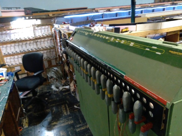
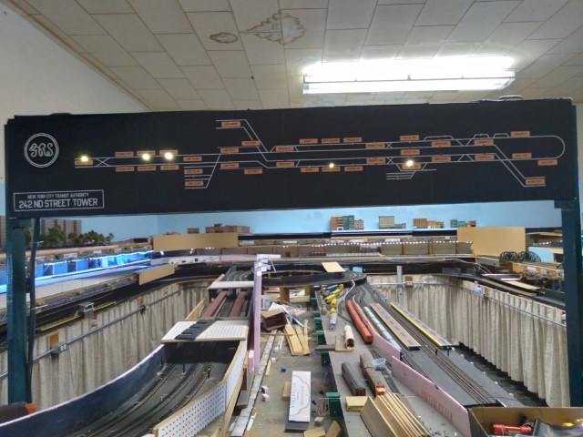
I built this machine after the GRS machine. the handles alternate up and down so that the operator does not mach his hand on an adjacent lever. The switch, signal or other appliance (de rail crossing gate etc) was in ts NORMAL position when the lever was not pulled. a lever pulled put the device in the Reverse position. These levers operate a SPST microswitch which controls the switch motor. I use only Tortoise switch machines which expect to be powered one way or the other at all times.
On my layout there is a common HARD GROUND, that is it is connected to the building’s ground leg. Without that there would be stray voltages on that bus. Therefor only ONE wire is required for each switch. It is either + voltage (Normal) or - voltage for the Reverse position. IN the GRS scheme, the levers follow the model board fight to left across interlocking plant. Signals (painted red) are at either end of the row of levers, the idea being you would align the plant from the exit inward to the entrance, and then you would be able to set the signals and if everything is correct in the plant the signal lever would be freed to reverse. Signals are always red until they are reversed when clear is displayed.
Like it or not, I’ll talk your ear off about my switch plan. For twin coil machines my levers could be adapted with a magnet on the lever which would pass a reed switch as it passes. you would need two reed switched for each lever one for normal and one for reversed. Yes the magnet would pass by both reed switches when the lever is moved, but only the last switch activated will move the turnout to the desired position.