My experiments with free-standing benchwork

Hello!

I thought to start a discussion on free-standing benchwork as I’m trying to figure out the best approach for my setup.

Most people are blessed to hang their layouts on the walls, but I only have 2.5 walls and a big open space with two columns. More details on that are in my other thread at http://cs.trains.com/mrr/f/11/t/260185.aspx

A basic sketch for a self supported peninsula looks like this:

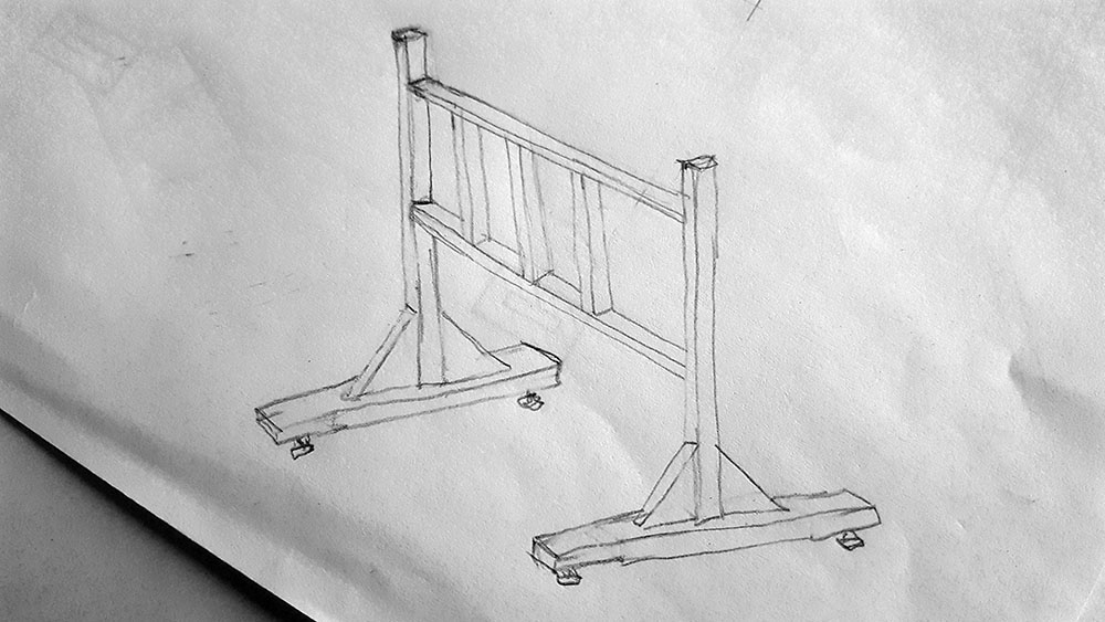
It’s a mish-mash of things I’ve seen elsewhere incorporated into one.

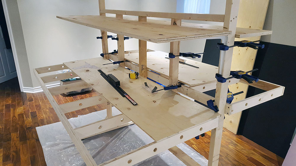
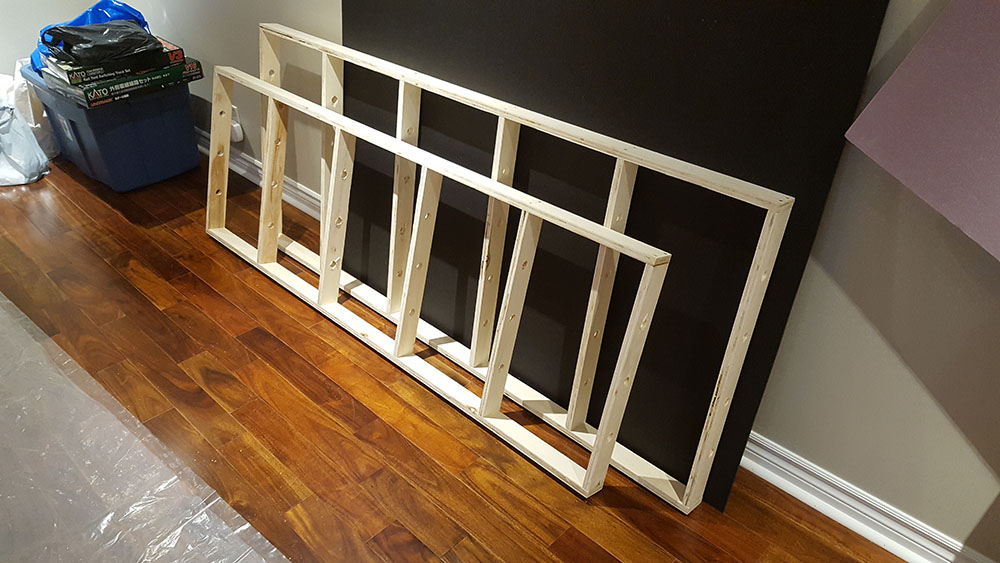
I gathered the materials, a combination of plywood (3/4" aspen) and dimensional lumber (2x4, 2x3, 2x6)

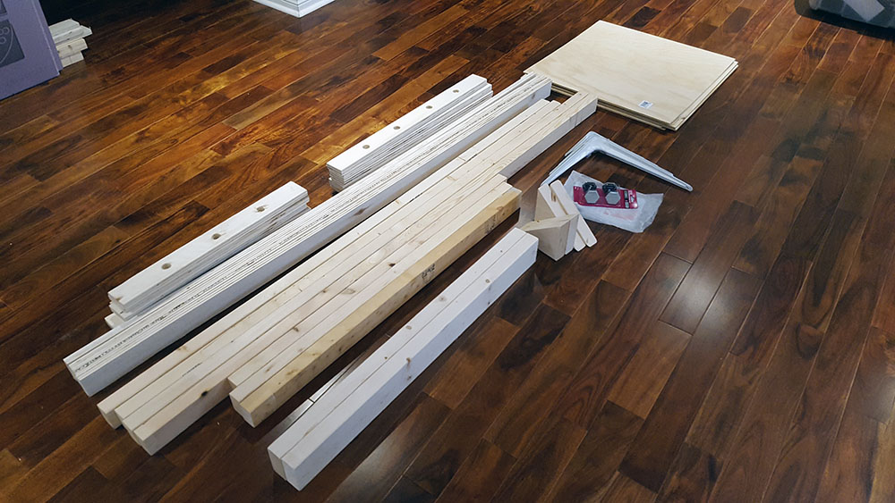
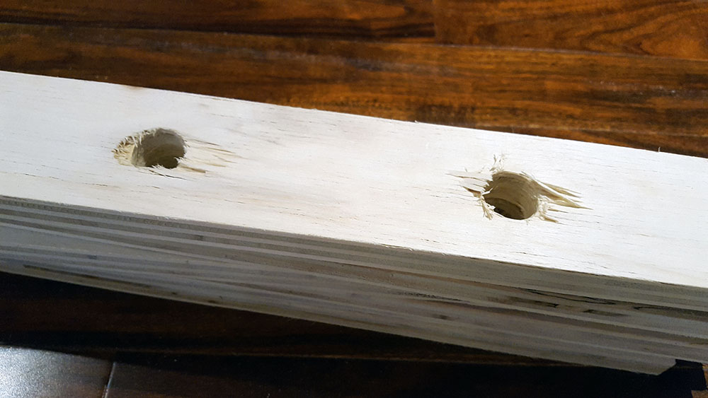
Already a lesson learned: don’t use Aspen plywood - it is way too soft for basic open framework and if you are not careful with the spade bit you get a mess like in the photo below.
Aspen would probably do well for a tabletop, being soft you can drive rail spikes into it, etc.

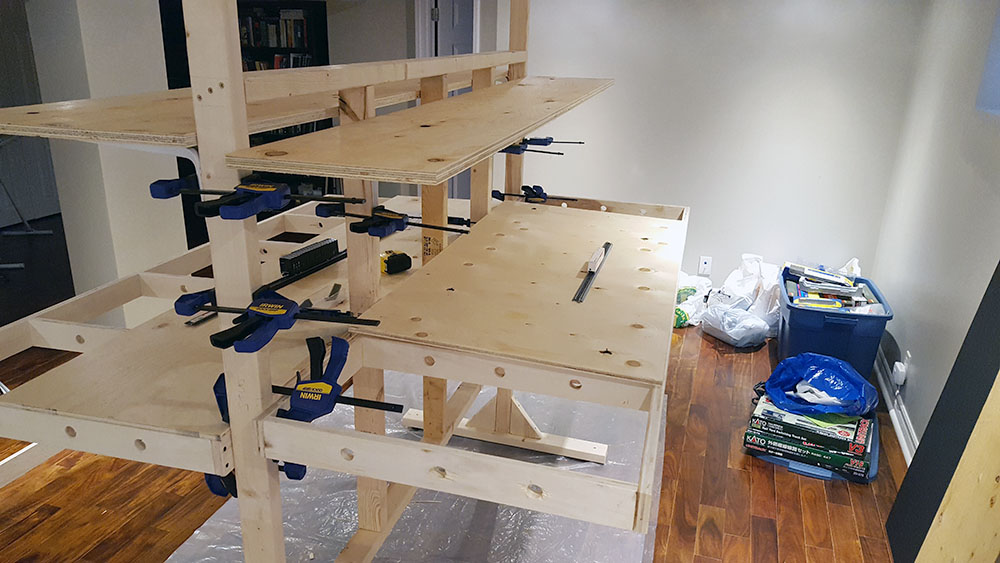
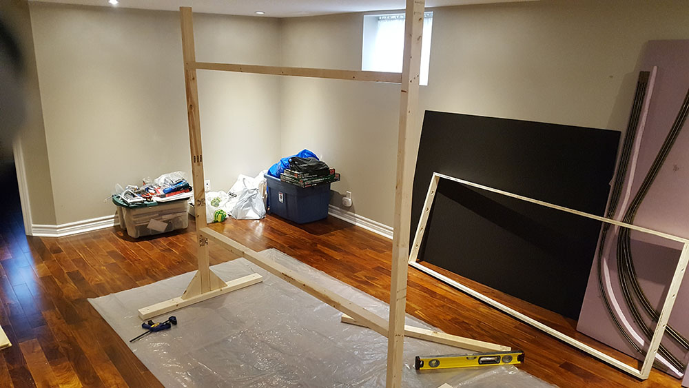
Progress on the way…

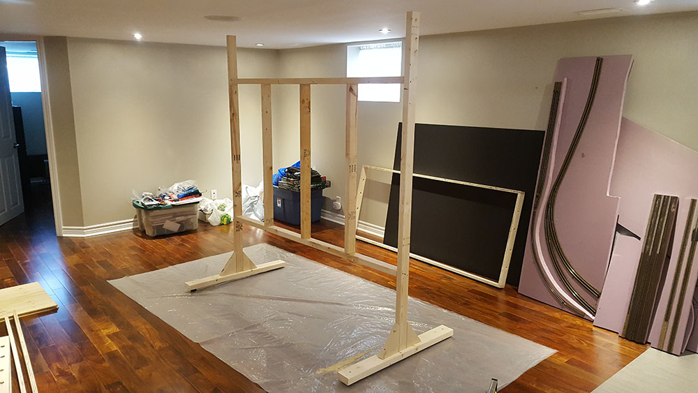
Larger module is 30" deep, smaller is 24". Intention is to test the depth against the height of double-decked setup and see what works the best in this space

Here, H0 scale track is on the left on the 30" module; N scale track on the right on the 24" module. I hate to say it, but I could fit a whole lot of N scale track into 24" depth.

That is really a unique approach to layout building. With the “feet” narrower than the modeling area I would be concerned about one side being heavier than the other and the chance of the whole structure falling to the heavier side. A soloution to your spade bit problem, stop drilling as soon as the point of the spade bit breaks thru the material. Turn the board over and finish the hole. Please keep us up to date on your progress.

Good point on the spade bit.

If lateral balance might be problematical, simply attach a box of rocks (or scrap metal) to the most lightly loaded horizontal leg. Where, and how much weight, can be determined by hoisting each leg with a spring balance.

Going by my own experience, any tendency for the box frames to deflect out of square can be permanently stopped by adding one diagonal element to the frame. I used a small steel girder, but could have achieved the same result with a length of baling wire.

Chuck (Modeling Centeral Japan in September, 1964)

Made a bit more progress today…

The left side is the 30" and 18" deep tabletops, at 40" and 59" respectively off the floor.

A (hard to see in the photo) 60’ box car is sitting on the H0 flex track on the main level, looking kinda big to me, in relation to the size of the module surface and the size of the room.

Sigh, a few of these cars and they’d fill the 6’ length of the module…

Similarly, on the right side a 24" and 12" deep tabletops, at 42" and 58" respectively off the floor.

An (even harder to see in the photo) box car is positioned on a section of Kato N scale track, both looking miniscule and teasing at the amount of railroading that would fit in 24" depth.

Main levels have 1/2" plywood on them, while upper levels are made with 3/4" plywood resting on common shelf brackets. This combination should offer enough clearance between levels without taking away vertical space.

Also to consider is that because there’s no open-frame benchwork on the upper levels, wiring will have to be done more creatively as well as mounting of the lighting system for the main level.

I used clamps for all instead of permanently affixing with screws so that the various surfaces could be moved up or down and test how heights impact visibility of levels.

In both cases at my eye level of 71" I can see all the way to the inner edge of the main level without obstruction from the upper level.

Since fascia is missing on all of the outer edges, I surmise once in place it would probably cause some interference in viewing all the way to the inner edge.

By moving away half, or full, step back into the aisle remedies that interference though.

Some mista

For thin lighting, consider LED strips. They are available in different white color temperatures (warm white, cool white, etc) as well as colors and also RGB. My intention is to use two white strips plus an RGB strip and maybe a blue strip to light each level. That should give me a nice bright daylight, as well as allo dusk adn dawn sequences plus night operation (the blue ones). These have been around long enough now that the technology is mature, the products are reasonably priced, and they work. The ones I put under the bottom shelf of my electronics workbench - well, the adhesive backing said it was genuine 3M, but I don’t trust it. On Amazon I found shallow U shaped rubbery mounts, they fit over the LED tape and have 2 screw holes. They produce quite a bit of light. On 18 to 24" wide benchwork, a double strip whould minimize false shadows and make enough light to read car numbers. The RGB strip tuned to white menas there would actually be 3 white strips during day operation. One blue strip plus the RGB strip on blue should be sufficient for night ops - cheap pen lights with uncoupling picks attached will allow operators to see what they are doing.

–Randy

A book that might be of interest

https://www.amazon.com/TilTable-Book-Tables-Model-Railroad/dp/0983579008?SubscriptionId=1NNRF7QZ418V218YP1R2&tag=bookfinder-test-a-20&linkCode=xm2&camp=2025&creative=165953&creativeASIN=0983579008&tag=bookfinder-test-a-20

@rrinker

That’s what I was planning to do - already ordered some LED strips to do a test.

I ordered Warm and Cool White, and a Blue, so I will do 4 rows of LEDs. Top will be Cool+Warm and side will be Warm+Blue. I also ordered dimmers for them so that they can be well adjusted.

Ultimately I would go with several rows of RGB as those LEDs can be individually addressed and controlled. Think rolling day/night across the layout. Ok, might not look as great in my layout size but still…

@DSchmitt

Thanks for the pointer, will check it out.

The RGB set I have - the coontroller is junk, it doesn’t allow enough brightness options for each color. The steps are very noticeable. I’ve decided to just build my own which will allow more gradual transitions between colors.

On a previous layout I mixed warm white and cool white flourescent tubes (2 tube fixtures, each got one of each type) and while looking up at the lights was very odd, the light it cast on the layout surface was actually pretty good. So a strip of each type LED may be a good option. The ones I have on my workbench use 5630 LEDs, they are brighter than the ones that use 5050 LEDs. The RGB strip I’m pretty sure is 5050 size LEDs.

–Randy

It’s not clear from the pictures, but are your modules held to the uprights only by screws through the rear girder? There’s going to be a lot of downward torque at the outer edges of the layout once fully loaded and especially if someone leans against it. I’d be a bit concerned about the layout drooping without either legs or a diagonal supporting the outer edge.

jim

Actually they were supposed to be held with gassets, but because the stud spacing does not match the spacing of the open-grid joists I will have to re-engineer it in the next iteration.

It’s a bit difficult trying to match the spacing on both pieces across large spans, without some very precisely cut wood pieces. Maybe I can get IKEA to start mass producing these which would make it easier. :smiley:

No need to overbuild. The whole point of keeping the benchwork narrow is that you can easily reach WITHOUT having to climb on it. No need for gussets every wall stuf. An occasioonal diagonal brace from a stud tot he front edge will work, at other locations some metal L pieces will sufficiently reinforce the attachment to the wall and don’t have to necessarily line up with the benchwork crosspieces. And as long as you aren’t planning to build scenery with concrete, modern scenery materials are pretty mightweight.

–Randy

You should look for information on Jim Hediger’s Ohio Southern benchwork. He used legs in an X pattern. I see the videos he did are now a part of Model Railroader Plus but you can see the X patterns in the teaser photo.

I have done this myself and found it not to be sufficiently rigid. The problem is that the “stud” in this wall you have built will bend in the wind like the tree it was cut from. I tried several ways to fix this, but in the end I had to attach to the ceiling to keep it from moving.

Far too much emphasis is placed on the weight of the layout and what’s required to support it. Supporting the weight is not the primary concern. What’s important is stability. The penninsula needs to built so that when someone bumps into it, it doesn’t move. Otherwise a small “hip check” into the benchwork will derail every car on both levels of the penninsula.

Another under building issue that often comes up is the size of subroadbed and the spacing between risers. Your subroadbed is going to sag between the risers over time. Any sagging is going to look bad, and the smaller your scale the worse the sag will look. A 1/4" sag is 3 feet in N-scale. Your models will end up looking less like trains on track and more like boats on the ocean.

You do in fact need to overbuild - by a lot.

On that 6’ length he builkt, if it has just TWO diagonals fromt he front edge back to the vertical studs near the base, the only thing that will happen with excessive weight is the whole thing might tip over. That can be fixed by making the ‘feet’ longer. Those are 2x4’s vertical, they are not going to deflect. My electroncis bench has 2 - a whole 2, 2x4’s - the wrong way - the 4" side facing front, holding up metal shelf track with 2 brackets for each shelf. Those verticals each have 2 bolts, one near the bottom of the leg it extends above, and one near the top of the same leg. I have some heavy equipment like power supplies on those shelves - the only deflection is the middle of the shelf, it’s one of those standard shelf pieces you buy at the store, less than 1/2" thick. The vertical 2x4’s, even though they are oriented the wrong way for minimal deflection, don’t move.

My previous layout,t he individual sections, even the ones that were 2x8 ft, standing alone in the middle of the room, on the carpet, were kind of wobbly. Integrate them intot he other modules running around the walls, and it was solid as a rock. The only place I needed to do anythign extra was one section that was completely standalone - with a liftout section on either side. That one was wobbly all the time, so I used a pair of 90 degree metal brackets and screwed it to the wall studs in 2 places. No more problems, even when I bashed my head (more than once) on the liftout because I didn’t feel like taking it out and ducked under (or almost under) instead. I think one boxcar derailed, once.

That’s perhaps one of the reaosns I’m not a big fan of L-girder - the hortizontal support is a screw run up throught he narrow flange of the girder into the narrow edge oc a 1x4 joist. Except where there are legs so the legs extend up and can be fastened to the wide part of the 1x4. That to me sounds liek it will be VERY wobbly. Box type construction, there’

I think I’ve seen a photo of the X legs somewhere, can’t remember where. I’m just not sure it would work for a multi-deck peninsula I plan to build. As the current plan is a G the peninsula is pretty narrow at places so X legs won’t have enough space unless I let them extend into the aisle.

Also, I’m going side with carl425 on the need to overbuild.

Last week I was at my local club, talking to two other members about building benchwork. All three of us were leaning on the layout. It was not intentional, it just happened, almost as a matter of habit or convenience.
The benchwork there is pretty solid, so it just stood there without moving. But I can imagine if it wasn’t…

I can see it, especially in N Scale, a hip check on any part of the benchwork that’s not robust will topple all rolling stock in that area like dominos.

Regarding my test build, the verticals are 2x3, while the legs are 2x4s.

@rrinker, let’s see your electronics bench? :slight_smile:

I built mine many years ago; 2x4s, survived a move, disassembly, re-assembly, feels like it’s built like a tank. Still need to finish setting everyting up, but because I haven’t done much electronics lately I feel I’m stuck in the past decade with the equipment I have.

What I still have packed away is an ERSA IR/PL550 BGA rework station, and a full PACE PRC 2000 soldering station.

Turns out, it’s not. The cookie-cutter roadbed makes a big difference – the benchwork just gets stiffer and stiffer as you go. L-girder is fine, open-grid is fine – but if you’ve never actually built with L-girder, you’d be surprised how well it works…

Also built like a tank - all 2x4’s and a solid core door top. I have another section that will come off in an L shape on the right to be my train workbench.

This is before my static mat came, plus since I built this about a year ago, I have aquired another power supply and 2 more bench DMMs. And not shown are my Fluke 8060a handheld or my EEVBlog Bryman BM235 handheld, or my Fluke 8012a bench meter. Oh and the monitor for the computer is now on an articulating arm to save bench space. There are LED strips under the bottom shelf to light the surface. The shelves just sit on standard brackets, so they come off, the verticals bold to the bottom frame, and the top is held on with 4 L brackets screwed in underneath, so it all comes apart to move - the door is quite heavy though.

I actually drew it all in 3rd PlanIt before I built it.

–Randy

Very nice, I really like your main surface, looks like a solid piece of wood, and how you used the shelf brackets to hold the three levels that tie into your bench studs.

I made my surface out of two pieces actually: subsurface is pine planks, while the top is hardboard/masonite. I knew top surface would get messed up over time so I made it replaceable. All I have to do is plop the plastic edge off the bench and replace the surface.

I put the LED strip as well, under the first level to light up the main bench area. My LEDs are mounted on a metal bar that swivels so I can adjust the angle they shine at.

To think that I designed and built this bench while living a two bedroom apartment, cutting wood and painting on the balcony still amazes me though. :slight_smile:

I built a whole layout in the larger of the 2 bedrooms of a 2 bedroom apartment. It’s all on my web site.

The bench top is a solid core door, $40 at Lowes. Yeah it’s not a solid chunk of wood, those doors go for $100+. However, it’s solid enough - it feels like a solid door when you knock on it, and it’s certainly heavy enough. But some hollow core doors go for that much, this was a bargain. I coated all sides with 3 coats of poly, with some light sanding after the first and second coats. I may run some shelves underneath around the back and sides for additional storage - it’s generally back far enough that I won’t smash it with my legs. The top is already offset on the base - the rear legs are flush witht he back of the top, the front sticks out about 6" past the base. That power strip is a Tripplite with remote switch - the power switch is mounted to the left front leg, I can reach under and turn everything on and off. Also under the front left is where I have the jacks for a wrist strap.

–Randy

45 supports or ply triangles Like the ones on your footing supports on your structure would not only be a good idea but a necessity, easier to do now than later when things start going South just trying to help I do like your concept, very cool