Like this:

Like this:
How about something like this:

The grades will be between 2-3% to get top town up to 4". It still is 22" min radius.
Thanks Chris, that is about what I just finished but I have put the grades going the other way just only 2" up on the back side. Here is what it looks like:

IMHO you should pay more attention to the concept.
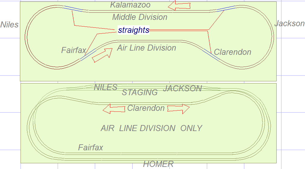
The upper drawing is probably your plan. Jackson and Niles are not modeled, you model shortcuts between the Air Line and the Middle Division. The only station modeled on your plan is Kalamazoo, a weird choice since it is on the Middle Division. For the other stations length is lacking.
The twice-around drawn by Chris is modeling the Air Line proper, with a few intermediate stations. Sufficient length to model three.
Your drawing does not give me a good idea about the space you have. Is it possible to rearrange the cabinets and bar?
Wish you luck, the reach-in issues would make me reluctant to go ahead.
Smile
Paul

Here is another shot at a twice around. Radius are 25" and 22" at the ends which would make them a little larger than the 4’ you have them now. Also the town that says 4" would have to be closer to 5" for the clearances to work. The town at 2" you can treat as an at grade crossing and an interchange point with another railroad. The openings in the dog bones could hide access hole which you would need to reach those back corners.
This also feels more mountain railroad than Michigan but it comes down to what you are willing to compromise on.
Chris
Reading the OP´s initial post, I gather he has not yet built a layout since his childhood days. A multi-level or multi-deck layout is far beyond the skills a beginner has. Building such a layout will most likely ending up in a ton of frustration.
The OP is well advised to look for something simpler, like the Mascoutah, Ill. layout.
Jay:
You will need a way to access the corners. Adding the triangles places your body that much farther away from the corners. I don’t think you can make the benchwork low enough to make the reach easy.
The layout you have drawn looks to me like one large town, with engine servicing on the right, with spurs and buildings scattered about randomly. If you are trying to model more than one town, you should try to group the spurs and buildings into two distinct areas.
You said that you have not built a layout since childhood, and may be trying to put everything you want into the space you have. A well executed layout that has a simple track plan will be more satisfying than a poor execution of something more complex.
The space that you have looks like it may be public space in the house, where guests might visit. The trackplan that Sir Madog Ulrich posted would make a very nice presentation.
I think you should consider adapting that track plan to your space, perhaps adding specific features of the area you are modeling. Its things like structures, bridges, rivers…the details… that you recognize from the area that tells you and others what you are modeling; not the trackplan.
Your designs still have a number of s-curves, particularly involving turnouts. These are places where opposing curves connect directly through at least one of the track paths. These are likely to cause problems.
For folks who have never designed a layout from scratch before, I always suggest some time studying John Armstrong’s Track Planning for Realistic Operation. This book will give you ideas on how each track you add can provide more interest for the long term. This, to me, is a better use of one’s time than many CAD iterations – but virtually no one ever follows that advice.
Best of luck.
Hello everyone.
I had to step back for a couple of days and evaluate what I was doing. Listening to everyone pull me in different directions was a little overwhelming. I have learned a lot in these past days about this and am thankful for all the good ideas. I understand that the space I have to use is less than ideal, but not everyone has that. I build as much bench-work as I could get away with without getting divorced. I also understand that I wanted to put more than I can manage into the layout.
So here it goes. I can’t move anything in the room that I have built around. I have made adaptations to the bench-work slightly to make this last design fit.
I understand the reach issues everyone has, and I don’t see that as a problem as the entire bench-work is on 6" casters and I move it to get behind to lay track and model scenery.
Here is the new drawing. All curves are 22" or close with the flex track. Hopefully the last as I am getting ready to model.
JW

I think this plan is MUCH better.
Most of the turnouts are towards the front, which makes them easy to reach during operation. The basic shape of the plan looks much sleeker and realistic. You don’t have to be married to the locations of the spurs or turntable at this point, since you may get new ideas as you lay track. You may also find that you might not want as many crossovers as you have.
With the reversing loops the layout has, the layout might be challenging to wire if you’re not experienced. You’ll want to read about how to wire a layout before you start laying track.
I agree, I think this is a much better plan. As noted above, there are reversing loops/sections, and will need to be wired as such. If you use an autoreverser, I think you can get by with one reversing section. I think you’ll be happier with all the turnouts within reach. I’m not sure you’ll need so many crossovers so close to each other, I see at least 3 within a (roughly) 6 foot length. The double crossover could be removed, unless there was some specific reason it’s there.
I see no issue with the placement of the turntable and roundhouse, but I would give consideration to relocating the turnout for it to the front of the layout. It’s quite logical for an incoming train to arrive in a yard, drop its cars, and the loco to head to the service area, letting the yard switcher handle the cars. In your plan, it reflects the loco traveling a few “miles” to the service area (and in some cases, this could be accurate), as opposed to heading “just other side of the yard”. A loco using the main to get from the yard to the service facility might involve getting clearance from a dispatcher to travel those few miles.
Anyway, the plan in certainly coming together.
Brad
I do agree with the crossover, it isn’t needed. My only concern with this design is that it is pretty much a mirror image on both sides, and wondering if that is a bad thing. I am trying to design something different for the left inside corner that works with the rest of the layout, and here is what I came up with that falls more inline with the Air Line.

That is the map of the area, and here is what I did:

I removed the unneeded switches on the corners of both sides, and kept the DCO, thinking the wiring would be easier this way.
John
Looking good. I lost track if you’re planning on DCC or not. You have two reverse loops, which will require at least one electrical reversing section. This can be automated with an autoreverse circuit, or controlled manually with a DPDT switch (the autoreverse is highly recommended if using DCC) The reversing section ideally should be at least as long as the longest train operating through it.
One thing I don’t see in this iteration is a passing/runaround track, UNLESS you use the tracks to the “back” of the layout as such. This might be prototypical (or not) for your line, but it will make setting out and picking up cars a hassle. This is why railroads commonly used single crossovers, spread apart, so as to create passing/runaround tracks. Putting the switches back, and removing the DCO shouldn’t really change the complexity of the wiring. You’ll still have 4 turnouts to control, and assuming the turnouts are not power routing, should need no special wiring considerations or track gapping.
Brad
I do plan on DCC, researching what one to get. I kept the DCO versus the 4 turnouts simply because of the coolness, and the spacing between between the 2 tracks is a good guide. In my research I read that insofrog turnouts were the way to go for DCC. I have looked at the auto-reverse circuit, and that also looks like the way to go.
I have one of the layouts with a passing lane/yard located on the back/top of the layout, and I will see how it goes when I start laying track to see if the curves can maintain the 22" arc and have enough room for that to fit. I took that area out to make the inside triangles smaller.
Thanks again for all the input. I will begin posting pictures when I start laying roadbed.
JW
Hello everyone, Thought I would post some updates along with pictures.

Green - Grades
Blue - 1" above table
Red - 2" above table
Orange - Spurs not in stone
I have a couple of questions regarding wiring. When wiring the inside loop, should I wire the feeds to go in the same direction or opposite? I figure I will need at least 2 auto-reverse modules.
Here are a few photos of where I am so far.


Just want to thank everyone for all there help so far, and look forward to hearing from everyone.
I just read all the posts, and I think your track plan is looking better. A few comments, though.
First, unless you are planning to do a yard on the left, those innermost 3 spurs are too close together for any industry.
Second, that “bubble” of track in the middle of the front just behind the mains is useless and a waste of money. The mainline crossovers to either side of it work for a runaround, and you would still need to cross the mains to get to the outer spurs.
If I were you, I would put the lead for the engine terminal where the “bubble” is now, and have a crossover in the left hand green track so that the engine terminal is basically where it is now. I would also suggest adding a single industry in the middle of the dogbone. I would also suggest adding a hill in front of the interchange track to hide the dead-end, and then maybe a one or two track coal mine behind the interchange, with the mine butted up against the hill and the track(s) going into the hill. Try a switchback on the front edge of the right end of the dogbone to use up some of the wasted space. Also, cut the benchwork to 1.5 to 2 inches from the track or about 1 inch from structures to make it easier to access and to eliminate additional wasted space (modelling nothing does not look good, and if you’re not careful, you’ll end up with a cluttered look trying to fill all that space.)
Oh, and you’ll need support under those crossovers or the tracks will sag. Remember to install auroreversers on the end loops.
Looks like the layout is coming along great. Have fun.
Thanks for reading and replying.
You are correct as the spurs on the left bottom were intended to be some sort of yard, not sure yet, but figured I would see how it looked. The bubble in the middle I have to agree, and I didn’t put that in, I am planning on some sort of industry in the middle, just don’t know what yet, I have to find one that fits the era and location.
As far as moving the lead to the middle, I don’t think I want to try and mess with crossing a graded track. (All the green colored track is grading approx. 2%)
I do plan on trimming the corners once the spurs are done, just don’t want to limit myself until I know what industry I will be putting where.
Thanks again for the comments and I will post some more pictures in a few days when I have more track laid. I am about 50% around with both mains.
JW
Instead of crossing the 2% grade, you could place a turnout where the right end of the bubble up against the crossover turnout (you may need to trim a few ties from each to get the new turnout to fit) and then put the crossing just before the start of the grade. It looks like you have a short flat section there that would work. It looks like a 45 degree to 60 degree crossing would fit. By moving the terminal a little more towards the back, you should have room for larger facilities. In addition, you would have room for a small diesel terminal in fromt of the engine facilities.
I wouldn’t recommend curving the yard tracks. You’ll have problems with coupling. Instead, straighten out the tracks and put the yard at an angle to the front of the layout. Don’t worry about the gap between the yard and the mains. Fill it with an interlocking tower and aother hill. You might want to consider extending the left end of the dogbone forwards a little, with at least a trianguar extension so that the new yard tracks will fit better. A one or two foot extension will give you significantly more yard space.
You might also want to consider adding another track or two in the back for staging.
Looking good!
Thanks for the perspective, and I think this will work when I get back around to that area, I started in that right inside corner with the mains, and am looping around the back.

As far as adding to the table, not much room to do that with the room constraints and such. A yard is a luxury that I might not be able to do, and as far a hills, not many in the area I am trying to model, so they wouldn’t fit well. I am planning on a river in the upper left corner crossing that area from the back edge to about the middle of the left side. As soon as I get the mains laid (I am about half way around) I will start working on the turntable area.
Thanks again for all the ideas and such.
JW
Looks great i also am modeling this area i live in Niles have you ever see pictures of the MAL rolling stock i know MCRR bought them as soon as the line was finished. I would like to have some decals made if possible. any help would be great.
Thanks
Mike MCRR