My First Track Plan in 30+ Years...

I have just returned to train modeling for the first time since my childhood. I have built benchwork to fit the space the wife has approved. My question is, how much is too much when it comes to track layout? I have been working on a design for a few weeks now, and now that I have it finished, it might be too crowded in the yard area. I thought I would post the drawing and see if anyone else has an opinion. Thanks for the time.

JB

I’m impressed with your early planning.

I recently completed the tracklaying on my new 5’ x 10’ HO layout. I tended to include a fair amount of track for a layout that size), for the main route, for yard storage, engine servicing, etc. It may be what some consider a lot for the space but it’s the track layout I wanted. Some specific comments related to mine that you might consider:

a) consider, of course, minimum radius, particularly on the main route, and how that interacts with space between the outside tracks and table edge. It’s nice to leave some room on the outside, for scenery, etc but that space allocation reduces the radii of the turns in a given layout space. Mine has 25" or more radii, which should accommodate longer engines and passenger cars, but won’t look as good with them as wider curves. Lots of compromises, including increased track complexity often reduces radius because of tradeoffs (in a given space).

b) plan for structures that will interact with track layout. In my case, an engine house had a certain track spacing (I had obtained a measurement that was off), a coaling tower needed 3 tracks, with particular spacings (when I had planned for two), a diesel fueling facility needed modification where I wanted to put it. It’s nice when you can obtain the building kits to measure the parts for the right track configuration.

c) a long straight run is perhaps not as nifty as a long gentle curve, which can add to scenery interest. I admit that I violated that.

d) MR reference books and NMRA guidelines are useful for planning track spacing; e.g., parallel mainline or yard trackage

e) adding multiple levels, if they cross over, can add lots of track (and hide some) if you want grades, longer runs (yours looks pretty good as is), etc. In my case, I went multi level mainly to increase the main run length (without crossings, another option at the same level), a

I would suggest you remove those two crossings that really serve no useful purpose. Instead, I’d recommend you simply have a double track mainline. You can then place a double crossover in a strategic location allowing each track access to the yard and engine facility.

You also might want to consider a few more industries. After about 6 months, most folks get tired of watching a train running around simply chasing its caboose. You might also want to check out some of the project railroads MR has done over the past several years. Most are well thought out and offer a good operational possibilities. With a little thought, most could be adapted to fit your space.

Good luck,

Tom

The biggest concern I see is the ability to reach the track in the upper corners. Reaching for derailments and even laying the track and building scenery will be an issue.

A basic design rule of thumb is to not have any track beyond 30 inches from an access point.

Unless you have access around all four sides of the benchwork, you may have to plan to cut access hatches into the benchwork near the upper corners, which will result in the need to relocate the yard.

Sorry, but that’s likely the best approach at this point. Its also best to work out a plan before you build the benchwork, to avoid significant issues such as this.

I see several things that could be improved. I would consider removing the crossings as suggested earlier and making it double track. I also see an “S” curve on the left side above the dark green structure, and another below the red one. The former can be fixed by using half-sections of curve, joined by a straight section between the two. The latter can be fixed by removing both pieces of curve, shifting the straight section to the right, and relocating the red building. The double-cross-over creates a reversing section, electrically speaking (I think? Looks again Scratch that, as it does not appear to tie back into the outermost track). The two “loops” will have to be wired for running in opposite directions, even if it’s all wired as one electrical block. If you plan on the “top” of the plan being against a wall, it will be an awful long reach to lay track, and work the yard (assuming this is HO scale). I would suggest having the yard switches within easy reach to facilitate uncoupling. I’m not sure if you plan on a roundhouse, or just having the turntable with “open” tracks. It might be more prototypical to have 2 of these tracks head back to the yard, both to act as a passing track, and to simulate separate inbound and “ready” tracks. If HO scale, I would strive for minimum 22" radius (I couldn’t read the designations) or larger.

That’s all I see at first glance. Maybe more as things are critiqued and pointed out.

Brad

Thanks everyone for the comments so far. A few things that I forgot to mention in the first post, Yes it is HO, and the total length is 16x6, with the middle section being 8x3. As far as the reach, I purposely built it lower to the ground to help with that, and for the grand-kids to see better when it is done. I am tall enough that I can reach all areas pretty well. Now the crossovers, I know they aren’t the best things to use, but I am trying to recreate the Michigan Central Air Line, as that is where I grew up. The outer curves are all 22", but the insides are 18", to try and make the crossings work. I will attach the map I am trying to come close to recreating.

Thanks again everyone.

Maybe it’s just me, but the middle looks more than 3 feet. I still say it’s going to be a long reach if it’s against the wall (and judging by your reply, that’s my assumption). 30" is a common maximum, and even that’s likely to strain a back after an extended period. If you plan to actually switch the yard, you’ll want it within reach to uncouple the cars. What software did you use to draw this? What brand(s) of track? Do you have certain pieces of track you are intent on (re-)using? I see plenty of potential with the available space and benchwork, but the proposed plan seems to waste a lot of space and scenic opportunity. There’s ways of using and incorporating crossings into your plan and still having a better utilization of space. One way would be to have spurs or sidings come from right and left, using the crossings in a “town” setting.

I’d be happy to draft up an idea or two and post them here if you wish. But I’d need more info on your operating scheme, both your prototype, and whether you have a preference to switching a town, or “watching 'em roll”.

Brad

Welcome back! I dont have any usefull advice for you except to say that last year I too returned to the hobby after 30+ years and am having a great time! Such a great stress reliever. Someone on here always signs off with “If youre having fun, then youre doing it right”. A great and true motto! Mark

Jay

Welcome back to the hobby!

My initial reaction is to suggest that although you may be able to reach all the track because you are a tall guy (so am I) you have to ask yourself can you reach that far for extended periods of time, i.e. when you are laying track or doing scenery. Being able to pick up a derailed car is not the same as laying track or doing ballast at the same distance.

I have struggled with the same problem in my own layout plan. I have hopefully solved the problem by keeping the layout narrow enough along the back wall were I can’t get behind the layout so that I can reach where I need to. (It still may involve the use of a cantilevered work platform.) For the other areas where the layout will be too wide to reach from one side, I have the advantage that I can access the other sides of the layout room walls. I am planning on using smooth bi-fold doors along the outside walls so if I need access to a hidden or distant track, I simply have to open a door to get access to the hard to reach areas. Granted the back wall of the layout will have a few seams in it where the doors come together but that is acceptable to me so I can get the depth of layout that I want.

I figure there will be one big disadvantage to the use of bi-fold doors and that will be controlling dust from the rest of the garage. I am hoping that the judicious use of weatherstripping will solve that problem.

Dave

First of all, a big welcome back to one of the finest hobbies in the world.

You asked for an opinion on your track plan idea - well, here is mine.

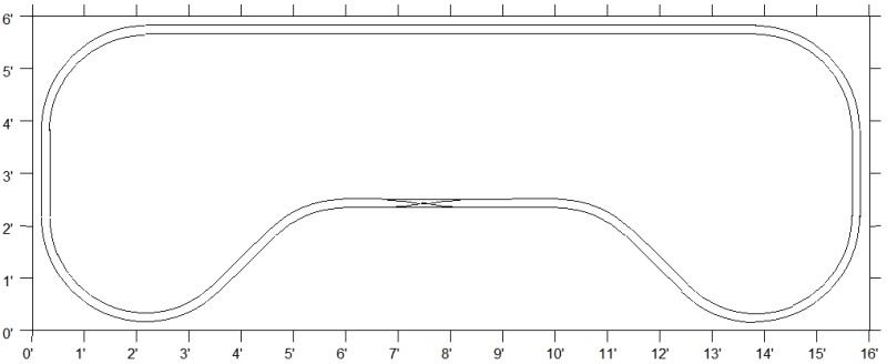
I see a number of typical beginner´s design flaws.

As most of the others have already mentioned, there are areas that are beyond the reach of a normal adult. I don´t see a way how you can work on that yard in the upper right corner, unless the entire layout is accessible from the back end.

A second issue is that you have planned your track way too close to the edge of your layout. Not only will you risk your precious locos and rolling stock being shattered on the floor in case of a derailment, it will also not look right. You should allow for at least 3 - 4 inches to include some scenery.

Most of the action on the layout is on the far end of the layout. Add to that the reach issue and switching will become a nightmare.

Roundhouses are always a nice eye catcher, but just having a turntable and a roundhouse without having the necessary engine servicing facilities does not make much sense.

I see only three spurs for industries to be served, for a layout of this size this seems too few.

There is no obvious reason for the track in the front to meander the way you have drawn.

Your plan does not include any staging facility. Staging is the place where we store or trains. Staging also acts as the starting point or destination for our trains.

A footprint of 16 by 6 ft. is an awful lot of reals estate for a layout, but I am afraid this plan is not making the best use of it.

This may sound very negative to you. I don´t want to discourage you, but a layout is always a quite significant investment in terms of time and money and therefore should be well considered.

Designing layouts is an art, which very few of us master. Although I am an old hand at designing and building layouts, I still have a lot of problems with “filling” such a large space.

What to do?

Good Morning everyone. I did forget to mention that I built this all on casters, so as far as modeling the corners and back sides, that is not an issue. I do understand the yard issue, and I put it there to try and get as geographically close to the area I am attempting to recreate. It doesn’t need to go there, I could swap the yard with the turntable and roundhouse, to make the yard more accessible. Nothing is set in stone, except the benchwork, and there can be some tweeking of that.

Earlier it was asked what program I used, and it was SCARM. I am always up to suggestions, as I haven’t purchased that much yet, except some rail-bed, the turntable, and 6 Peco #6 turnouts. I do have some old track I am trying to use, mostly Atlas snap track.

The important part is to recreate the Air-Line area of Michigan Central Railroad. The buildings that I put on there are just random squares I put on to give it some color.

Then the question becomes - what elements of the area are most important for you to recreate? Clearly, even if you had a whole basement, it would be difficult, if not impossible, to recreate a whole town or junction on an inch-for-inch basis. As modelers we have to use selective compression and be a bit more choosy about what we include. As such, are you wanting to model a particular scene, station, industry, junction, track arrangement, or just try to capture the “flavor” of the place? In short, what is it that makes the Air-Line so recognizable? Are you working from detailed city maps, or just a general county map? The former will be better for modeling a particular city, as well as help us see what you are trying to accomplish. The latter might be better for us to tell you things like “That region didn’t see [XXX], but saw plenty of [YYY]”, giving you an idea of what kind of traffic you might expect. Someone more familiar with the region might be able to chime in with “Such-and-such industry operated in [Town] from [Year] to [Year]”, if you don’t have this information already.

My chosen prototype went under in the early '30’s, and I’m working in a 9x12 space, so I’m having to do a lot of compression. Some of the towns still exist, as do historic photos. My intent is NOT to model the trackage as it was the day it was removed (and I model 25 years later anyway), my goal is to capture the flavor of the town so that if/when someone visits, or sees a photo, they’ll light up and say “Oh! I’ve been there! I never knew it had a railroad!” I want someone to be able to look at photos of the real town, and photos of the layout, and have to look many, many times to find major differences.

Case in point: Clermont

Thanks again for all the input… Sitting here watching football and redrawing a few things. As I have found out, trying to include too much is not always a good thing. I wanted to have 2 complete loops within the parameters of keeping as close to the map I have chosen. That doesn’t seem to be working well, so I have eliminated the second loop, and instead used part of that as sidings, and others as dead ends for workable areas.

The biggest reason I chose this particular region is it is where I grew up, and I remember my dad telling me stories on how he would hop the train in the morning, go to the next town, and then catch the train back in the afternoon. The track was removed in the early 80’s, as it hadn’t been used since the mid 70’s. At some point in the mid-late 50’s, it was upgraded to handle large diesel freight to bypass the larger towns. Everything I have read, and there isn’t much that I have found since I started this, was that this route was built to be a shorter route between Detroit and Chicago bypassing Battle Creek and Kalamazoo.

What the Air-Line had was many small towns along the way, mostly farming communities and very little industry. From what I have found, the line was used to move freight to Chicago, but also had local passenger service up until the mid 50’s. This was the main reason I wanted to have some sort of double track all the way around, but space has made it impossible to keep a 22" radius on the inside track.

Anyway, Here is take 2 of what I am sure will not be the last revision, Thanks again everyone for your help.

John

I’m no expert but here’s my personal take:

I tend to have a pretty good eye for spatial issues and looking at most of those spurs on the left side, there’s virtually no space for anything to go next to those tracks. That goes for most of the layout. There’s not exactly room for things that aren’t eaten up by track, roadbed (while the TRACK is one width, you actually need closer to 150% of the space you think you do), and clearance (which pushes that close to 200% of the track width). You’re not only running into no space for buildings, there’s limited space for trees or anything else bigger than a phone pole.

I’m going to step outside the box of what people normally suggest. You said you already have benchwork constructed. I don’t know if you’re planning on sectional track or what. If you are (and this is a wild stab because the plan looks made out of sectional), go out and buy a bunch of various sizes of curves and straights. Or go the cheapest way and print out a ton of full size pictures of track. Either way…and here’s where things get a bit different…don’t focus on the whole plan. Just piece together the outer loop. Tweak it until you’re satisfied with JUST THAT. On a tabletop layout with a continuous loop, its as big a constraint on the rest of the layout as the footprint itself.

Once you’re happy with your mainline, you can start organically placing spurs, crossovers, passing sidings, what have you. While doing that, look into structure kits you want to use. Cut out pieces of paper the size of their footprint to use while you’re literally growing new branches of track.

No plan survives first contact. Rather than design a plan then get frustrated when 80% of it doesn’t work like it did on paper, go hog wild and don’t have a plan. Its also a great learning experience because you’ll learn what works and

John,

First off remember it is your railroad so you can do whatever you want.

But since you asked here is what I got:

The biggest issue you have is the benchwork you have built, the use of the turn-back loops. With those it immensely restrict the plan as you have seen.

Also the turntable also eats up a lot or real estate and with you repeatedly mentioning the MC Air Line branch, the only locations I found that would have a facility like that are Jackson, or Niles. If you just want a turntable to show off locomotives then fine, If you want to recreate the Air Lines branch I would cut it out.

A 6x18 space gives you a good about of room to do a nice feel of the Air Lines branch, here is what I would do, this gives you a place to store trains and then to run them out over the railroad twice around before returning to the yard. Each siding could be a town that has a mill or freight house with a small passenger station.

This plan is 6x18 with an operating pit to use the most of the space. The back three tracks can be a staging yard hidden by a backdrop. This is by no means a complete plan but just to give you an option on something you can do with the same space you have but with a different benchwork configuration.

Good Luck,

Chris

Edit: here is something I found about the Air Lines route:

http://www.michiganrailroads.com/RRHX/Stories/ModernizingNYCAirLineForHighSpeedFreightService.htm

I took the liberty of drawing a potential double track main “outer loop”. It includes the double-crossover. Minimum radius is 22", drawn using mostly Atlas components. All “inner” curves are 22", all “outer” curves are 24". There’s plenty of room for a yard, spurs, and TurnTable and Roundhouse (not added yet. Wasn’t sure if you wanted TT/RH on right or left side of layout). The town(s) could go a little further in. Switches would be within reach, the tracks on the sides and back would have no switches. Track centers are 2" On-Center. This leaves you plenty of room for scenery, towns, industries (if any), hills, trees, etc. Granted, this would necessitate some modifications to your benchwork, but the mods are minimal and give you more radius to work with. Sharp eyed observers will note the “outside” track does have 22" curves on either “end” of the double crossover (24" can be substituted if needed)

Drawn using XTrackCad and exported as a BMP

Brad

Hi,

i would pay lots of attention to the contribution by Chris Stilson. He adresses the reach-in issues and in his plan I can imagine a railroad passing through 3 villages. If one of them is Clarendon, with its engines service facility is up to you.

The link to the AirLine site is awesome. Bottom line is a different attitude towards planning. You are starting with model-railroad ideas like i need two loops (ovals) so i can have two trains running at the very same time. While Chris started with the idea to incorporate a long main with several stations (passing sidings), along the line; hence the twice around. Jackson and Niles are supposed to be staging terminals.

BTW a drawing how your layouts fits into your space would be very helpful to explore alternatives for your benchwork. Changing or rebuilding your benchwork now might be better then finding out its shortcomings the hardway later.

Wish you luck

Paul

Good morning to everyone who has taken the time to help me here. Chris, while I would love to have more space to update the bench work, I am restricted by the room I am building in, which caused me to build in a flattened dog-bone shape. The reason is that I have to be able to get around the bar that is located in the center of the middle section giving me 2 ft clearance around it. The upside is that it is a short distance for a drink. I found this layout and it is what I began with. I could have gone a couple of feet longer, but I felt that would not allow me to acquire more space in the future from the better half when I get the chance to expand.

I did find a mistake in my initial bench-work drawing, I had the sides only 5’ instead of 6’, which makes them deeper than I originally drawn. I do plan on putting a 1’ triangle piece on the inside corners to help and make the transition from the outer 4x6 areas to the inside 3x8 a little easier.

Paul, you are right, I have imagined Jackson on the right, and Niles on the left. With Kalamazoo to the top, and the Air-Line along the bottom of the center section.

I had read that link before and it has a lot of great info, my only problem being about half way through it, the text is overlapping making it hard to read.

The issue with 2 loops was

JW,

I know that the tons of good advice you´re getting here can be overwhelming and discouraging, but don´t let that happen to you. Layout planning is not an easy game, sometimes even a little frustrating. But, IMHO, it is more frustrating building a layout for years and investing a sizable amount of $$$ into it, only to find out that you will not be happy with the result. This just happened to a friend of mine, who recently took down his layout, after working for more than 8 years on it. Taking it down and salvaging the parts took two weekends …

The form of your layout you have chosen has a number of issue to it, which are a possible cause for future problems, both in looks & atmosphere, as well as operation. The loops require a fairly tight radius (yes, even 22" is fairly tight) and have to end in an S-curve. S-curves always are an invitation fro trouble and should be avoided wherever possible.

I understand that the bar cannot be moved, so you need some aisle way there.

A dog bone design won´t eliminate the S-curves, but minimizes them:

Just food for thought…

Just a piece of straight track the length of the longest car between opposing curves mitigates the S-curve.