I recently inherited a fairly nice HO model trainset with lots of neat scenery, etc. Last week I built a stand for it and hooked up the controller. I was suprised to find that even though it has been sitting idle for many many years, all of the electronic track sections work after I cleaned them. I bought a model Thomas Train for my little girl to run on it. She’s really the only reason that I’ve gone to this much trouble so far.
Anyways… I digress. Apologies.
Despite the suprising functionality of the track, I have constant derailment problems at about four or five places on curves where two track sections meet, because there is a sudden 5 - 10 deg angle change in the rail orientation. How do I fix this? I’ve noticed that I can nudge the rails with firm pressure and they will move into better orientation with each other, but then they spring back. The track has been imbedded in a really nice gravel material, so I’m hoping that I can fix this issue without avoid ripping track sections up.
Hello. How nice that you are doing this for your daughter. In the end, she may be doing it for you…you may get hooked.
It is possible that the curves are very tight, and that the metal joiners, if they are there, have splayed over time. Or, perhaps you can see plastic joiners? In any event, the curve can be restored just as you have done, with some pressure down the radius toward the centre of arc, and then you must use track nails to keep it in place. Otherwise, you will have to carefully lift the track for a foot or two and then use acrylic latex caulking in a very thin layer to hold the track in position. Even then, you will have to use the nails temporarily and perhaps some full cans of food or drink on their sides atop the glued sections to keep everything flat and pressed into place where there are no nails.
One other possibility is that the joins have separated enough, or come out of alignment vertically to such an extent that the flanges can find the edges and pick the rail heads, thus lifting and derailing the truck or the entire engine.
Rail tops must be in line vertically, and when you sight along a curve at a shallow angle, say from 9-14" above the curve and a couple or three feet back from it, the curve should look smooth and devoid of any sudden kinks. So, if you place a straightedge atop the troublesome sections and backlight from behind the tracks, you get your eyes down to rail top height and see if you can see substantial light between the straightedge and the rails. If you can see a considerable gap, and it is along a curve, you can be assured that this is a likely problem. You will have to shim up the dip with cardstock, thin wedges of plastic from containers that scissors or office supplies might come in, such as staplers.
In many ways, we all have to learn how to tune our tracks. It just takes some thinking, some experimentation, and some steely nerves. Everything done in a controlled a
I think I already am hooked! I can tell it’s a fun hobby.
Thank you. Your tips are much appreciated.
Track nails, huh? I’ll see if I can pick some of those up today and give it a shot when I get home. Right now, we can’t run some of the most-fun sections (such as the bridge & tunnel) because the train always derails.
If there are metal joiners at the trouble spot a soldering iron an a bit of solder might do the trick. All you need is a small pencil type iron. you might need an extra set of hands, as well. Push things into alignment (using something other than your fingers), touch the iron to the joint, touch the solder to the joint right next to the iron (technically not right on the iron, but nobodies going to shoot you!). Once the solder flows, remove the iron, but hold things in place (obviously not with your fingers) for a few seconds to let the solder solidify. You are looking to get the solder to flow into the joiner, so do this right at the base of the track.
You didn’t say what the railroad is built on, plywood? a hollow core door? an old table?
It sounds like you have warpage…the track sections are uneven because the base they’re on isn’t level. If this is the case, simply pushing the track sections into alighnment and nailing them down will work, but you also need to check EVERY connection, those pesky rail joiners bend, twist and work loose and will cause you to have misalighned track and track that isn’t level, i.e., a bump at each join. This will make even the most forgiving of locos to jump track.
You want a smooth, even joint between each section. No rail higher than the one it’s joined to, or wider\narrower than the one it’s joined to. And a nice tight fit is preferable also, but this may cause problems later if the base you’re using expands, like during a high humidity period, it will kink your rail joints if it gets too humid, and you will have problems with locos\rolling stock tracking correctly.
The easiest way to tell if you have bumps in the track joins is to run your finger along each one, do you fell any sharp points? bumps? if so, check the rail joiner and see if its connected right, [both rails inside the joiner, not one in and one over\under the joiner], and check the alighnment also. I’ll bet you’ll find the problem and correct it and be running that Thomas in no time.
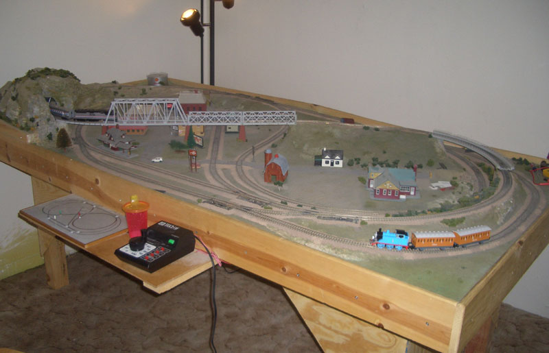
I really appreciate the help guys. Here’s some photos:
le’ Trainset. See Thomas dutifully rounding the lower bend.
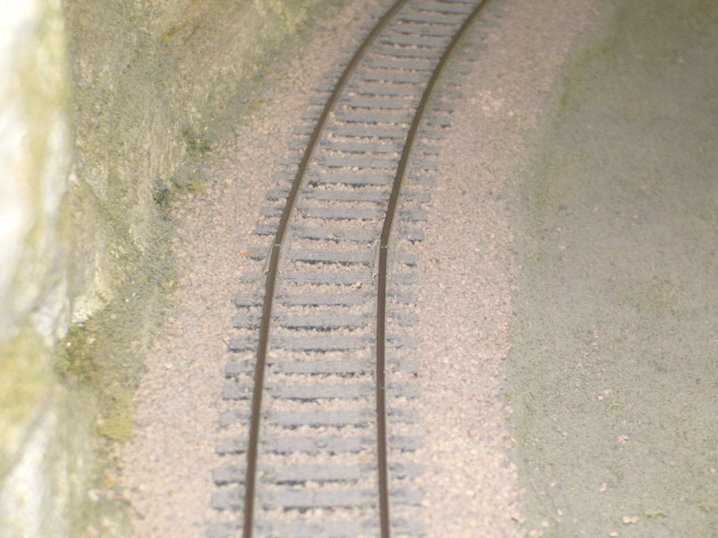
The problem: purely horizontal kinks. No vertical kink / vertical misalignments
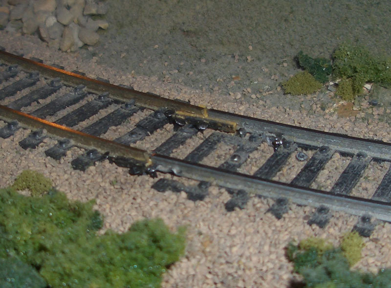
The solution, very very poorly implemented
I bent the rail and drove some nails to lock down the position,
but I get the feeling that somehow I did it wrong. It’s sure looks
ugly and out of place compared with the rest of the workmanship
on the track, but the train does run on it.
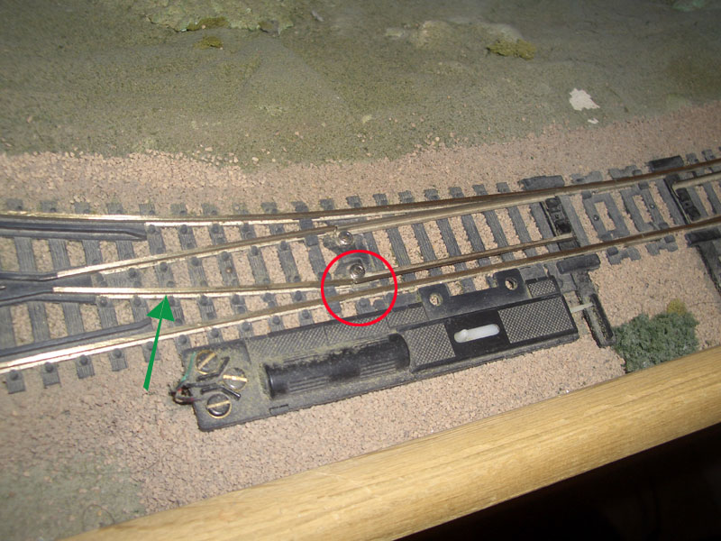
New Problem: No voltage on track section w/green arrow
I’ve narrowed down another problem with the track, which was
causing the locomotives to stall on the track at a couple of these
switches when taking the curved track. Using my voltmeter, I
discovered that the section of track indicated by the green arrow
was not being charged (even when the switch was actually in the
right position, not like in the photo, LOL). Anyways, I notice that
there is a conductive plate underneath the joint marked by the red
circle. I suspect that it needs cleaning. Any ideas how to do that?
I think a little dab of solder might have done the trick, but if the trains are happy for now you can learn more later. As far as the switch, I’d be tempted to add a jumper around the red circle. But first make sure power is getting to the moving part, otherwise getting the two parts more reliably connected won’t help anyway.
YOu can see the kink in the first, more distant, photo. What I would do, if it can be done relatively easily, is to deflect the closer track into more of a curve, that is by pressing the entire track to the left in the photo. It is currently too straight.
Often, only one or two nails strategically placed are all that is needed. If the ends will align with each other, even when you reorient the curve 4-6" back from it by adding more of the desired curvature, then place your nails at the new deflection to maintain it, and try to paint them the same colour as the ballast. Mix some acrylic paints until you get close, and then dab the heads.
The hinge in the turnout, where the points rails hinge to take their positions closer to their stock rails, are corroded or so loose that they no longer transmit power to the closure rail, the rail you have designated as green. (Italics are all proper names for the parts of a turnout)
You will have to attempt to clean the hinge, perhaps by a conductive penetrant or by tightening it very carefully with some taps using a drift pin or punch…very tricky, but turnouts are the most failure prone and replaced parts of most model railroads. Failing that, and rather an easy fix, is to drill a tiny hole beside the affected closure rail and run a bared-end copper wire to its inner base and solde the wire there. Run the other end to a power connection that you will have to provide, and you are okay…just be sure to get the power orientation right for that rail…positive or negative if in DC current, or right track wired with all right tracks.
That gap in the rails in the 3rd pic looks like it might be causing a problem…is there a rail joiner on both rails? I can’t see any on the nearest rail, and the track on the left side of the pic looks like it was cut at an angle. Very poor fit there.
The switch definitely needs cleaned…if you have a hobby shop close by that deals in trains they will have a product called RailZip…you put a couple drops on and let it sit for 12 hrs and then run your trains…no need to wipe anything up, just let it dry. It will penetrate and loosen any corroded parts and restore conductivity to tarnished\corroded parts.
The table itself looks pretty sturdy, so I’d say it’s just some misalighned track and some kinks\joints that are causing your derailments.