Right now my scenery plans are minimalist. The 1/4" wide slot in the middle of things between the two center boards will help locate a view block that I will fashion into mountains from foam board.
The ground cover will largely consist of spray paint for now, as I’m trying to avoid stuff that tends to shed easily when moved around.
I’ll likely fashion several hills to supplement the center range of them. I may provide a grade to climb up to a mine or logging camp. There may be a little Sculptamold involved if I can figure out a way to make it stick to the PVC.
In part, this is because I need to get this finished enough to display at our train show at Lincoln Square downtown in a month, but also to help keep things portable and easy to set-up.
Portability is a challenge for sure, for the base, the track and the scenery. Our club had portable modules, but we stopped the road show because all of the challenges involved. It’s now a permanent structure in our club. I started building a portable O scale layout, which is made of two 4X6 panels. It’s not quite done yet - I need to add more trees to it. The base is fiberglass with sand added to it. The track is not permanently laid. The layout is sitting on its side in one of my garages now (summer picture below). The base is quite stable. As you point out yourself, it’s not really necessary for HOn3, but I tought I would mention it to the readership.
Looks good, but heavy. You said it’s fiberglass, but what’s the frame made of? Not criticizing, because we all have different needs and goals, but one thing I wanted to be sure of was making the whole mess easily portable by one. For me, the 2x4 panels are about the top end of what I want to have to handle nowadays.
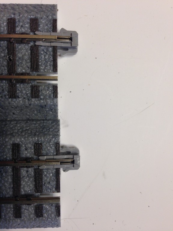
Re Ulrich’s caution about the potential for the connectors to hang up unless they had enough wiggle room, here’s what I did. The original connector is at the top and the one I modded at the bottom.
What I did doesn’t jump right out at you, but is very simple. The outer “wings” of the connector have a triangular nub on them, top and bottom (or both sides looking at it from the perspective of actually laying track down.). This is what “locks” them in place and needs to be overcome by rocking the track piece side to side when separating it from another single piece of track. As Ulrich helpfully pointed out, there’s no way to go side to side when you have multiple pieces crossing to the next module when all 3 are fastened to the same module that doesn’t allow each track segment to be individually worked free.
I took a file and smothed down that sharp angle on the nub on each side of the connector. Depending on how far you grind/file/shave it down determines how “grippy” the connection will be. I may have to take off more, which I’ll be able to determine in the next day or two when I get the track connections on the connecrting panel laid so I can test whether this resolves the issue or not.
Meanwhile, back to laying track. Here’s how I supplement the grip provided by the contact cement. As I mentioned before, I drilled up through all the “nubs” designed to take a track nail to permenantly hold it down. After the cement set, I drilled downward through these holes I made, allowing me to run sc
Mike, I really like your approach and I am following this thread with interest. I may build one!
Yes, my O scale project is based on very different assumptions: the modules can be carried by two able-bodied people. It is built on a wood frame, mostly 1X3 lumber with plywood using the cookie-cutter approach. The fiberglass is supported by a screen structure. I would say that each panel weighs about 60 pounds, and is meant to be carried on my trailer. It has two loops of different levels and can accomodate O scale, On30 and HO scale (tracks are not permanently laid). So very different than yours.
Interesting concept you have there. I take it it’s basically designed as a multi-scale roadbed and you lay whatever track fits the situation? Gives you some options. 60 lbs isn’t bad for 2 healthy people, but storage is still awkward. That’s part of my problem, I’ve got too much model RRing stuff stacked up “temporarily” in my garage right now. A member of our diuvidion passed away last year and left us about half a dozen Timesavers and a ~10x10" base for a portable layout, plus a bunch of other stuff. We’ll put it to use or find a good home for it all eventually. So a new 4x8 that didn’t break down for easier storage just wasn’t in the cards. I may join up this one with oine of the HOn3 Timesavers. That would be a good combination of roundy-round and swicthing action that would cover a lot of bases for a public display layout.
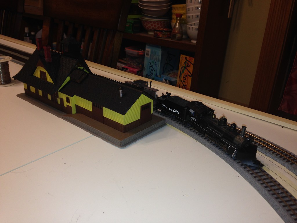
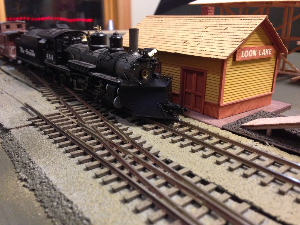
Did get some model building in during all this. Put together an old AHM Rico station kit, an itch I’ve been waiting to scratch since I was 15. Picked up a kit for $10 at our local train show last year (this year’s show is March 28 and 29), so it’ll be on display this year on the new layout.
Not a very good pic but it depicts the first train on Friday night, too.
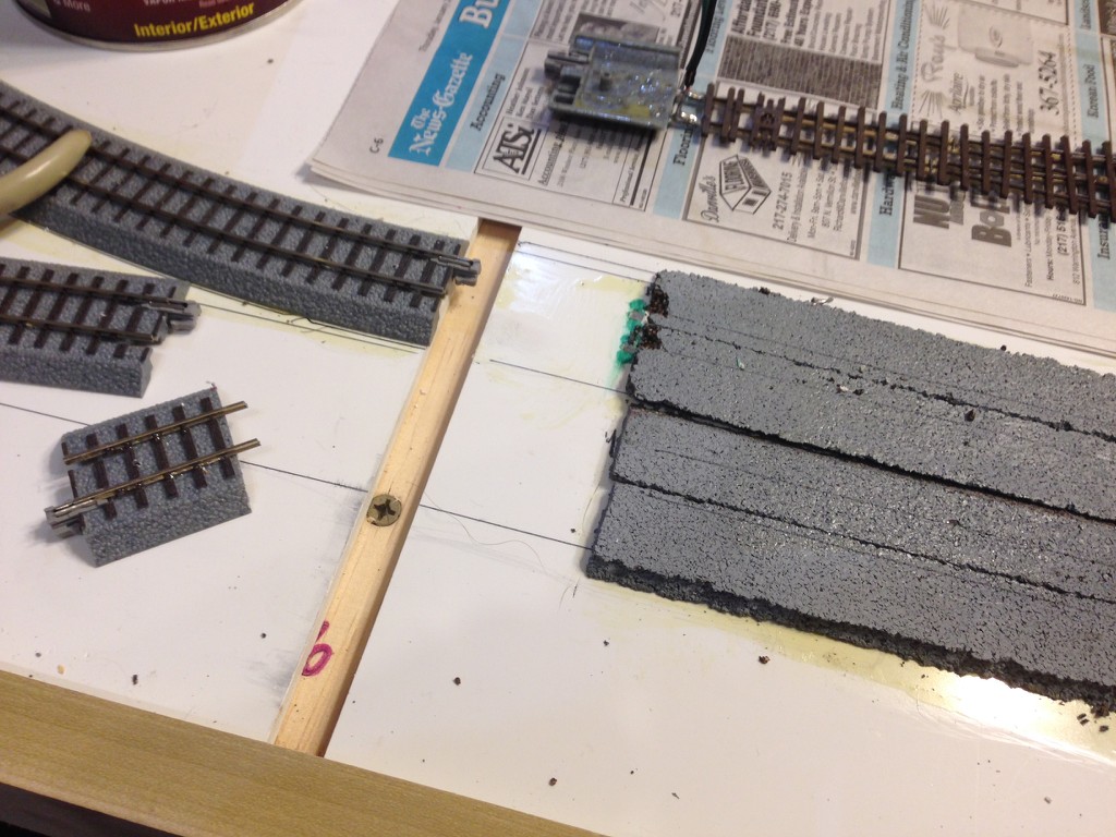
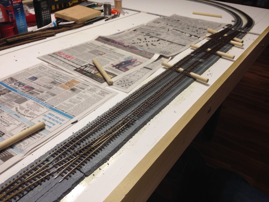
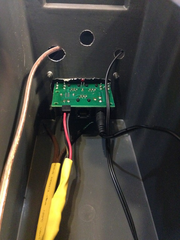
Last evening I laid the track on the other side, then I have to acquire more materials. And I’ve got one bad connection I’ve narrowed down but not found yet, but that’s for later today. Here’s some more construction pics and tips. Here you can see where I’ve laid the cork for the flex track after painting it to match the Protraxx roadbed color. At the end, I left space to accomodate the cut off ends of the straight Protraxx track sections that make this easy - at least once the build is done it will.
You can also see the holes for the power wires that feed the rest of this panel IDed with green marker. Using the connectors saves needing another means to power a bus for track power. NS rail is especially conductive, so you wouldn’t want to do this for a large layout, but for a 4x8 no problem.
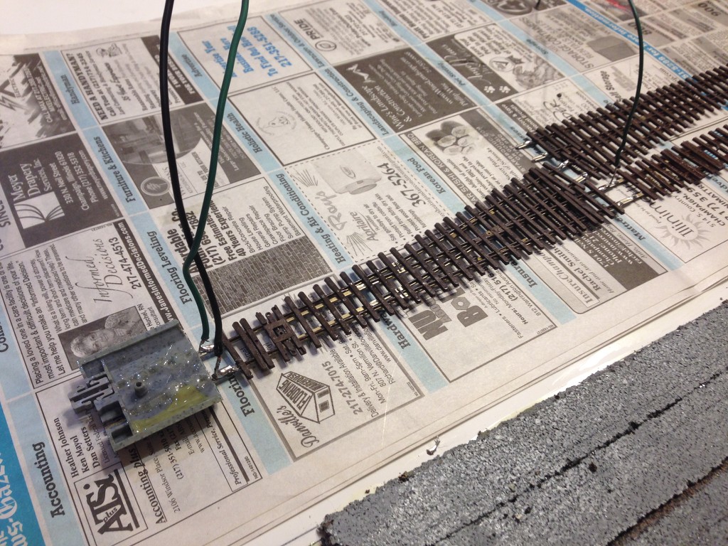
Next is a fabbed uo section of track with the power feeders attached.
It’s also gooped with contact cement and drying until ready to set. Next is how you keep thiungs in control so you can locate things accurately as you do that. The dowels prevent premature contact between the base and the track, then you pull them out as you place things in contact.
I found my bad connections to be in a couple of spots where I had to slide the rails in over one of the connectors sections I had to epoxy down. This simply required closer inspection and it’s easier to clean up if it sets first, then the tip of your knifeblade can flick the misdirected glue off the end of the rail. Everything is now going roundy-round properly. Then it was time to disassemble to deal with a couple of issues.
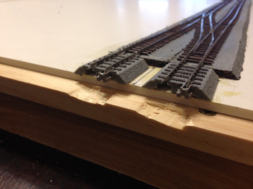
To accommodate the slight additional height added by the “security screws” I added to hold the Protraxx track sections down, I notched the crossmembers below the transition from one panel to the next. If you have wiring attached underneath in these places, you may also need a notch or two.
The panels did come apart easily with a satisfying click due to the mod I made per Ulrich’s caution about them hanging up. So long as you treat them nicely, they should last as long at they would ion the other track Kato makes. They are also replaceable if you do happen to snag one. This pic show how compact the arrangement is once disassembled.
The space the panels take up in storage would be about 2’ x 4’2" x <4". The frame once it’s broken down is longer (~8’4"), but not that big either. This limited space needed for storage emphasizes some of the benefits of using the Genesis panels.
Once I put it back together, things still worked well indicating we have a solid roadbed to build on and verifying the basic utility of the design.
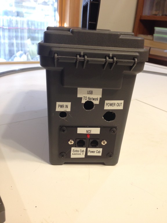
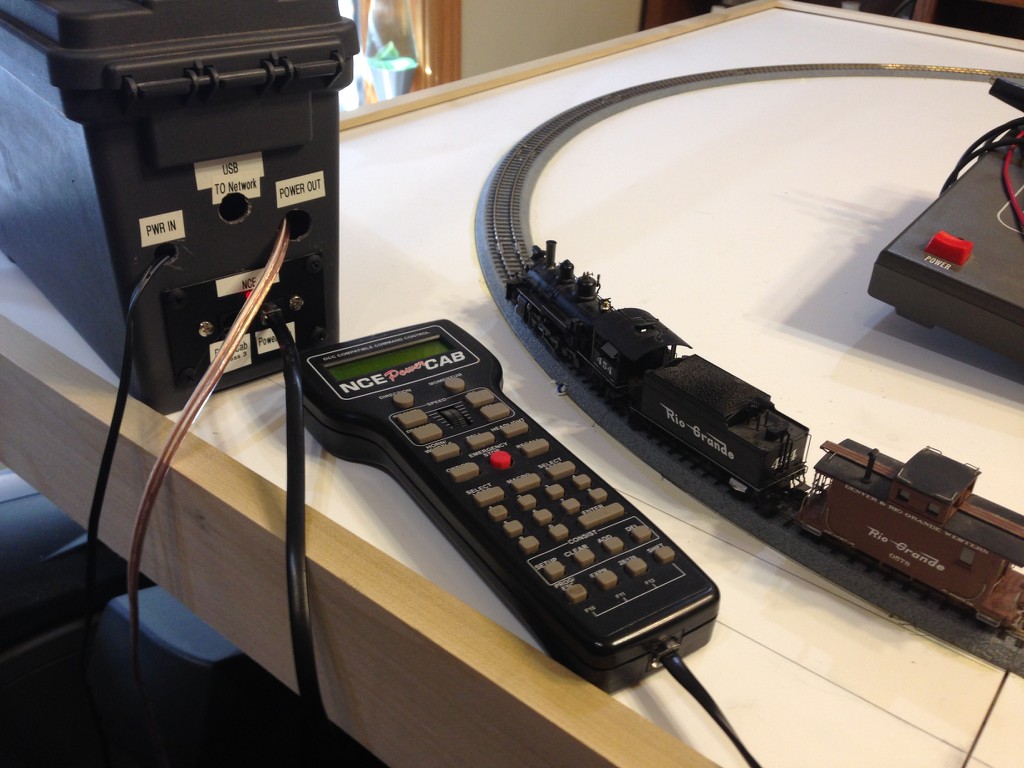
I hacked together a DCC system from a Harbor Freight plastic ammo can and a NCE PowerCab I used on my programming track.
A look inside, where there’s room for the hammerhead and all the cables.
I’ll eventually add some UTPs so the second throttle can plug in and walkaround the layout. Obviously, I can also swap in the DC powerpack if that’s needed instead.
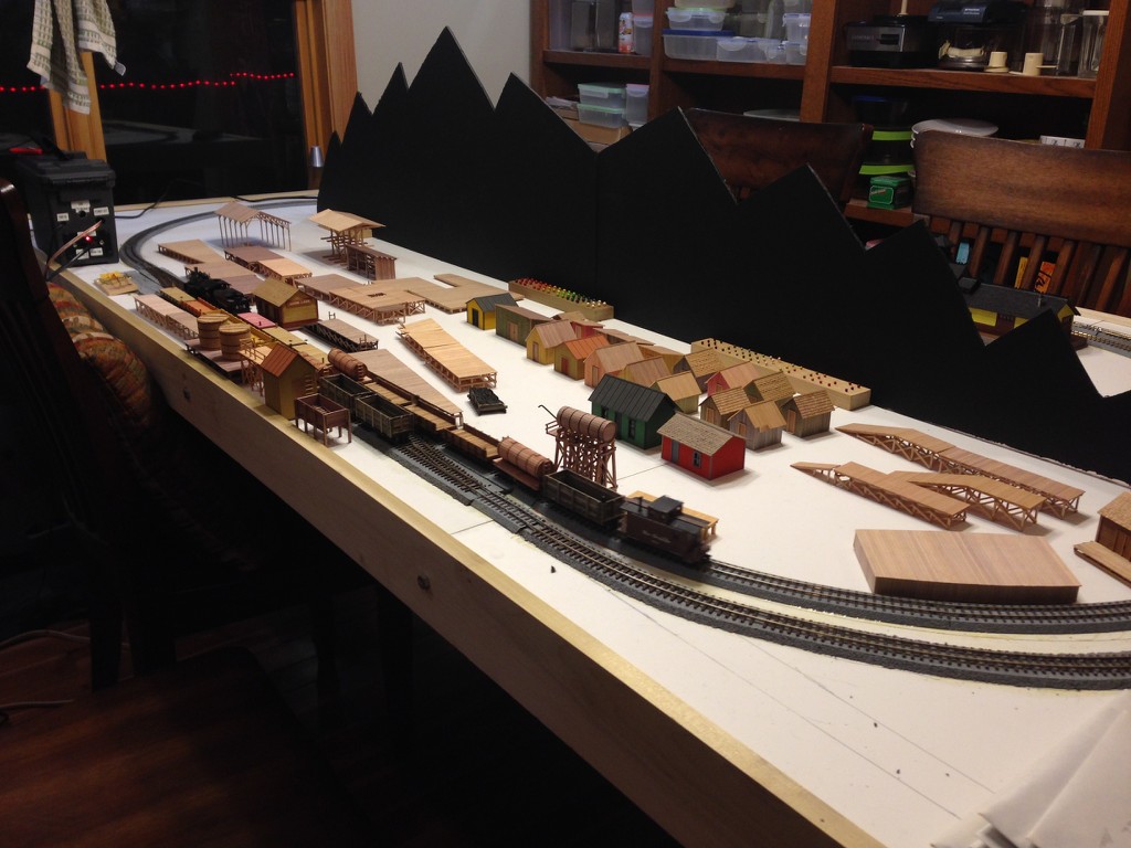
Also made a start on some scenery.
Given the need to break things down and store them, the topography will remian fairly flat, but also acts as a viewdivider.
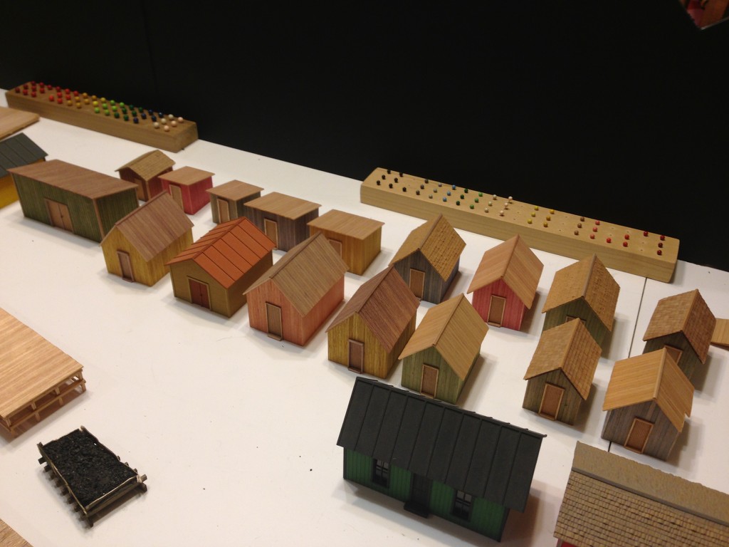
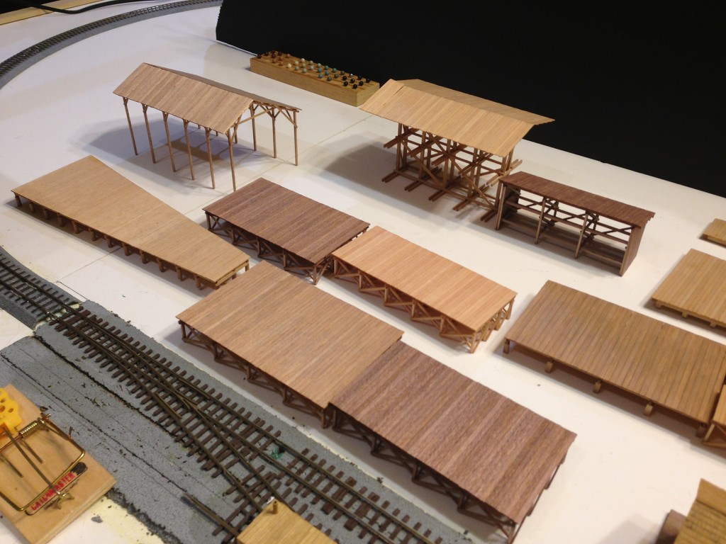
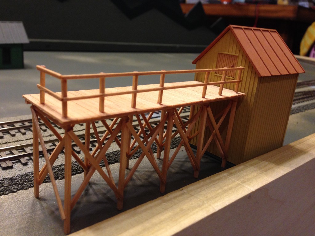
All the structures that have suddently popped up? They part of the donated Miller collection. Bob liked to build tiny meticulously constructed sheds and platforms.
This was the first time I have been able to get things out and evaluate what we had. I picked out about two dozen representative examples that I think should be curated as part of a permanent collection. We’ll likely evaluate the others for distribution internally so those who knew Bob can have a small memorial to him on their home layouts.
While looking things over, I believe I came up with a fitting name for this display layout. It will be the Millertown & Loon Lake Railway and thus a tribute to his efforts and work over a long life as a model railroader. One of the structures is the Loon Lake station.
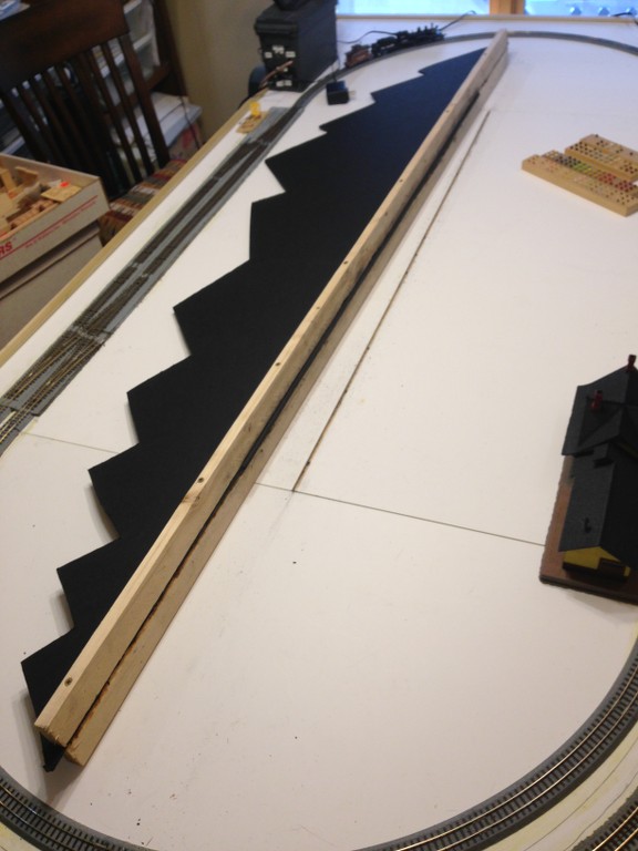
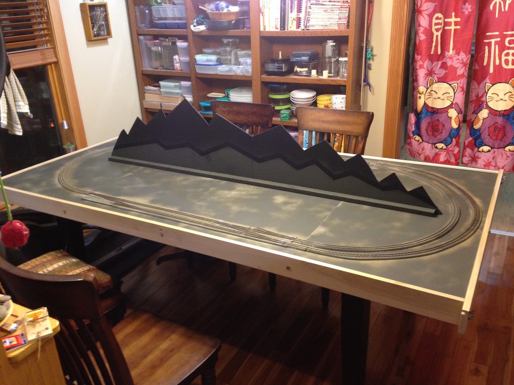
It was “scenery day” at last. Here’s where I started, with a mountanious scenic divider made from 3/16" black foam board and some 1x2 stock. The foam board was sandwiched in between the 1x2s with just less then a 1/4" protruding. This fits in a slot created to locate it between the two middle panels.
I painted some dark green to start it today, will add some more green/browns plus a snowcap or two on the highest peaks. I also painted the track and a “groundcover” base on the panels.
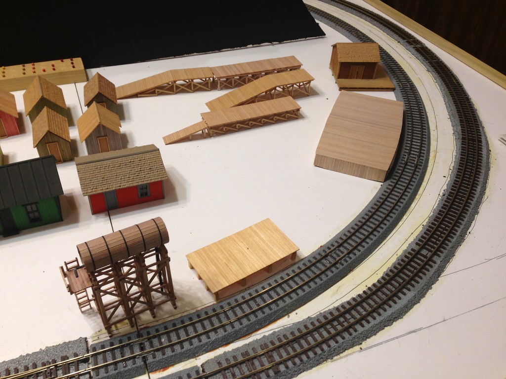
After drying and finishing cleaning the tracks, I broke out the structures I am proposing be curated from the Bob Miller collection. This includes the iconic Loon Lake station.
Here’s the water tower begging for just a little more detail.
Nearby was a tiny icehouse and icing platform.
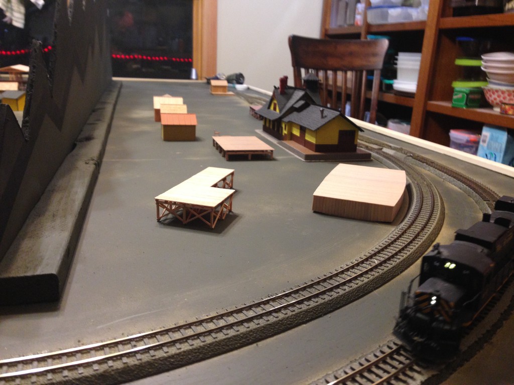
Circle around the mountains we reach this burg. About this time, the layout name came to me. This line is now known as the Millertown & Loon Lake Railway. Here’s millertown.
More scenic detail is sure to come down the road. Right now, attention is turning back to finishing the track.
Wow, that project is progressing quickly! I am very much impressed about how you are managing to give a second life to these really nicely built structures.
Sorry about the delay in updates on this project. I intended to show it at our local train show (Lincoln Square Train Show, scheduled for March 28 & 29) that we (the Illinois Terminal Division, NMRA) but…you know the story…CANCELLED. Eventually, when “normal” returns it will go on display. For now, you’re stuck with the virtual tour.
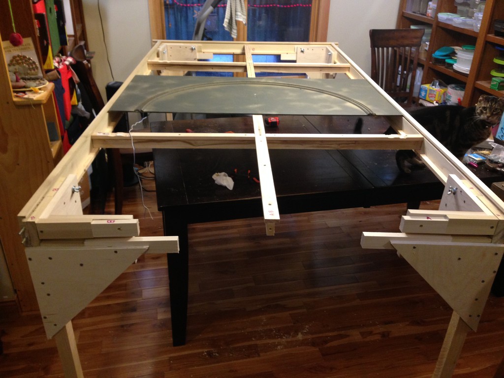
Putting legs on worked well, as they interlocked with the corners to provide a pretty stable result. Here’s a view of the frame with legs, with the end crossmember pulled off to allow the panels to be loaded.
These end views show where you load your panels, sliding them along the slot in the framework that holds them.
This does require some attention to keeping the legs upright, as removal of the end does make things shaky, but it’s easy enough to load. Here’s a close up of the end panel going in place.
I oriented the middle panels perpendicular to the end panels, as this reduced the number of required cross-panel connections simplifying track construction. This also allow the mid panels to drop in without the need to slide the whole way in along thr groove in the frame.
Once assembled with the scenic divider in-place, there’s a nice canvas on which to execute the sidings, scenery and other aspects of model railroading.
I should’ve taken more pics once the spurs off the main were added. You can see some of it behind the Millertown station.
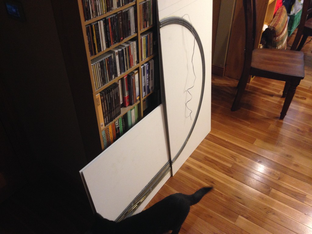
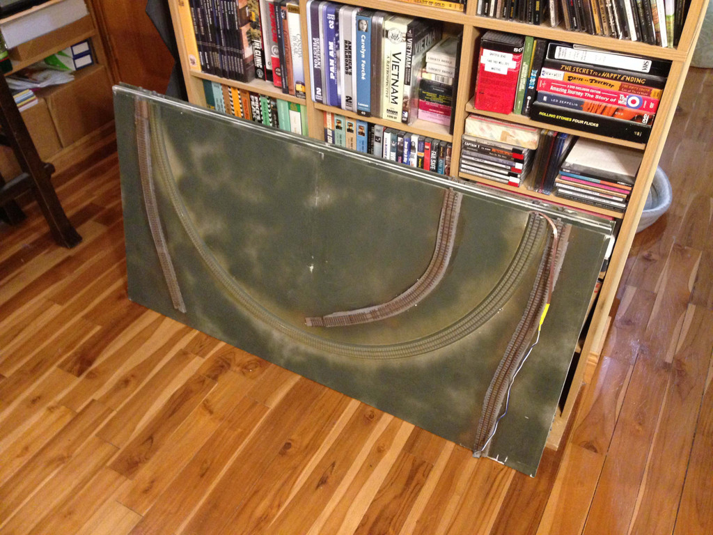
But the whole thing with the track/tabletop is that it doesn’t take much space, a seen here with all 4 panels stacked up tioegther, so this will allow us to get pics of the trackplan. Notice how little space the actual layout takes up without the frame. Any place with suitable table top can substitute for bringing your frame if need be. The wire draped over the top here is the sole power connection, all other connections between panels are made by the Kato connectors.
That’s one of the end panels. You can see a spur track on it’s left side and the slightly meandering line on the right side is what connects to one of the HOn3 modules built by Bob Miller.
These next two are the two mid-panels, where most of the added spur trackage went. I plan some logging and mines to privide traffic from the sticks down to the Miller module, which will host a sawmill and a ferry dock.
This one is Millertown. The station site sits next to the swicthback that gets the logs from the woods.
In the end, what’s really standard for my project is the use of the Kato Unitrak connectors and the Genesis PVC panels. This should work in scales from N to On30, basically anywhere there’s track that supports the Unitrak end connector. The Genesis panels actually need no support or framing, it’s more about making it convenient for the operator. Since I planned stand-alone operations and want to conect with a series of non-standard or standard modules, having the frame made sense. It’s also the case that in HO (or larger) scale, you need most of the four foot width to stand on its own because most of that width is needed to support 18" or larger min R.
In the end I failed to be as precise as needed to allow the end and mid-panels to swap locations. I came close and it is doable, I just feel it wasn’t worth the trouble once I got to the point of realizing it wasn’t qute right.
Mike, pardon me for adopting the role of a devil´s advocate here, but I still fail to see the benefit of your benchwork idea versus a much simpler, light weight construction method using 4" Styrofoam, clad in 1/8" hardboard for protection. That stuff is incredibly strong, doesn´t sag amd weighs next to nothing. It does not require a complicated support, in fact, a couple of saw horses and 1 by 4s would do the job.
I have seen layouts built that way in all kinds of scales.
The main advantage is that the layout is less than 1" thick (with the Caboose throws being the only high points) although most of it is only 1/4" thick (the thickness of the Genesis panel itself) to 1/2" (the Genesis panel plus the Protraxx/Unitrak) thick. The stack of 4 panels for the 4x8 is less than 2" thick, so significantly less volume than foam would be.
The PVC Genesis panel is also structurally much easier to mount various items to, like the screws I use to reinforce the sections of Protraxx that form the end connectors for track across the gaps between the panels. The Caboose throws can be similarly screwed tight to the Genesis panels. Trying to similarly mount items on foam of any kind can be an adventure.
The Genesis panels do not require any support or edge framing to protect their integrity. Foam kind of needs a frame around each panel to protect it being mashed or gouged, although you could get away with omitting it if you’re careful about storing and using it. Any table top at a suitable height will support Genesis board. My frame is somewhat more complex than sawhorses, but this was in part an aesthetic decision. I just wanted it to look good for public display and to be self-supporting. Now that I have the frame, I could easily make an entirely different layout (N, HOn30/HOe, or On30) from another set of Genesis panels, so that investment in the frame’s materials and labor can serve multiple needs.
And if you do use foam on sawhorses, then the layout will tend to need to be all on a single panel or on multiple panels larger than the 2x4 Genesis panels. A set of thin 2x4 panels is easier to transport that a 4x8, of course, but also easier than a 2x6 or 2x8, especially if 4" thick foam was used. I’d tend to think that most of those could actually get by with using 2" thick foam, though halving the extra space needed to store and transport the foam vs the Genesis panels.
A thought on the sculpty mould question try mixing some PVA glue with it slop it on a piece of scrap and see if it sticks PVA seems to stick to anything so might help.
But it may mess with the chemistry and take longer to dry.
That could work. I think it would require building and shaping the Sculptamold into the needed landforms off the layout, letting it harden, then gluing it to the PVC Genesis board. Otherwise the moisture in the still damp Sculptamold could interfere with the PVA drying (I like Titebond III Ultimate.)
Low relief land forms might work for me, but my actual plan is to build them, then simply lay them in place when the layout is displayed in iorder to minimze storage space and provide some flexibily. Others may find this works well to take some of the look of Nebraska “off the table” so to speak.
In that case it might be worth looking at how the wargames fraternity do their terrain and adapting that to something usable for model railroads they seem to use a lot of blue and pink foam no idea what the difference between the two is
It has to be light weight for easy transport to games and resiliant to cope with all those Ork’s, Goblins etc tramping all over it so may be worth some investigation.
Great tip about wargaming. Our rental house tenant is a big wargamer, orcs everywhere. I’m not sure he does 3D yet, but he does cast a lot of stuff somehow. I should ask to sit in to learn next time I get the opportunity. Might be some gold to mine there in that regard.
I actually was already planning on using foam, with it forming the bulk of the scenery while Scupltamold formed a layer over it. My layout is mostly like that, except it’s stuck with a heavy permanent frame. Here I just want hills I can easily throw around.
I think the color difference is only brand name, with blue being Dow and pink being whoever owns the Pink Panther brand (darn ol’ CRS) [:(] [swg]