I read that Consolidated steam locomotives (2-8-0 wheel configuration) on D&RG narrowline tracks had only 2 of the 4 pairs of driving wheels flanged. This allowed them to better negotiate sharp curves and put less wear on the track. That makes sense to me.
Which 2 axles would typically be flanged? Would there be any time that the non-flanged wheels were completely off the rail in a tight turn? Was that ever done on long standard gauge steam locomotives? Was it ever done on diesel locomotives, like the double UP units?
The four wheels of the outer two axles would be flanged.
Regarding a flangeless wheel shifting sideways and passing completely off of the rail:
All wheel suspension on locomotives has mechanical systems to equalize the loading on diesel power trucks or steam locomotive drivers. Loading must be equalized for power to be uniformly applied to the rails by each driven wheel.
Since the track has elevation irregularities, the wheels must be able to move up and down while maintaining uniform loading. So with this equalization, a flangeless wheel that ran off the rail head would drop down onto the ties.
If the flangeless wheel were prevented from moving up and down, it would ride up over a hump in the rail and lift the two adjacent flanged wheels off the rail and cause them to derail.
Incidentally, I can’t think of any internal combust
Drivers without flanges were traditionally known as ‘blind’, and you will find many references to them if you search using that name.
We have discussed what is necessary to keep these drivers from derailing on this forum before, including ‘doubling’ the rail on curves to ensure adequate bearing surface. In some cases the blind tread was made very wide to keep it from dropping off.
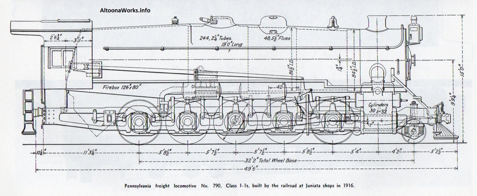
Much of the perceived need for blind drivers was reduced by introduction of the controlled lateral-motion device. If I recall correctly, the PRR I1 2-10-0 had three sets of blind drivers before lateral motion devices were installed (on the 2nd and 4th driver pairs); the center main driver remained blind. This on a large engine with no trailing truck or tender guidance of the rear of the frame, operated routinely up to 50mph.
I have seen a picture of an extra rail installed on a sharp curve to support blind drivers that would have dropped off the running rail. I don’t remember where though. Mark Vinski
showing the middle three pair of drivers as ‘blind’.
[#oops] Make that a 2-10-0 {Decapod] My mistake, shows me why the eye doctor says I need new glasses…[X-)]
There is also a really good one of AT&SF # 1 (nee132) now on display at the Kansas Historical Society Museum in Topeka. I was used by AT&SF until 1961, when it was placed for display (with a Drover’s Coach and Co. Office Car) with the Kansas Historical Society. The photo link below shows it in operating condition in 1961. @ http://www.rrpicturearchives.net/showPicture.aspx?id=2996203
Sam: You will recognize from simple arithmetic that ‘the middle three pairs’ on a 2-8-0 doesn’t add up right.
Remember the PRR I1s I posted about a few hours ago? Look at the drawing name of the file you posted, count the drivers, and tell me if it looks familiar now…
About eleven years ago, my wife and I camped up-Island near a a logging camp called Woss. Until about ten years previously, the outfit had run summer excursions with their old 2-8-2. We found it parked on a short stub track near the road into the lumber yard. I had not noticed the blind drivers, but as we both walked back to the turnout, I couldn’t help but notice how impossibly sharp it was at the frog angle. “No way…!” I exclaimed to my wife. I turned and said to myself, “Unless…,” and we walked back the 70 or so feet to the loco. Sure enough…
I am familiar with blind drivers, and have seen the blind tread made extra wide to avoid dropping off the rail, but never heard of adding extra rails on curves to pick up a blind driver that drifts off of the normal stock rail. Was this done by just adding a second rail of the same size as the main running rail; and adding it alongside the main running rail with the bases of the two rails touching? I guess the bases would have to be spaced apart to accommodate the spikes. I assume that the extra rails were added inside of the outer rail of the curve, and outside of the inner rail of the curve. Can anyone provide a picture or drawing of this?
The flanges are to the outside because of the torque that would be applied by the inner drivers if the flanges were on them. Rip the rails right off the ties! On the outside drivers they are leverage to keep the engine from turning sideways! The engine could twist off the track easily if the flanges were on the inner drivers.
The axles that have the flanges determine the position of the locomotive on the curve. If the inner axles had the flanges, the locomotive would be less stable in position and could oscillate from side to side.
The flangeless driving wheels often have wider tyres than the flanged wheels and this appears to be the case in the photo. This makes them less likely to derail. They are still conical in shape which causes them to move to the centre on tangent track. while allowing them to move across the rail head in curves.
Yes, there should be a pipe in front of the front driver. A few engines had pipes in front and behind each wheel or just in front of the front couple of drivers and behind the rear couple of drivers.
I’ve looked up the data for the Deutsche Reichsbahn (pre-1945 German State railways) Class 50 decapods. They were similar in dimensions to the PRR decapod shown in a previous post. Built to the tune of 3141 examples, they were as ubiquitious postwar as Ford Model T’s in the 1920s. Anyway, they had a distance between driver centers of 65 inches, a wheelbase of just over 30 feet, and could negotiate curves with a minimum radius of 460 feet. The first and last driver axles had 25mm (one inch) of sideplay, and the center axle (the driving axle) had flanges that were 15mm (0.60 in) thinner than those on the other axles. This seems to have been the typical arrangement of German mainline locos of the period (late 1930s), probably because the minimum radius wasn’t too tight. Goelsdorf-inspired designs usually had two axles without sideplay and the rest with different amounts depending on their position in the frame. I don’t think blind drivers were used much, German designers rather used mechanically more complicated arrangements like Luttermoeller axles - the end axles were driven not by side rods, but by cogwheels centrally mounted on the axles from the neighbouring axles, which allowed them more sideplay and some degree of radial steering.