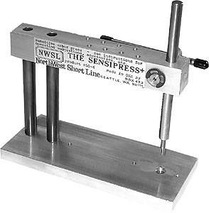
I’m interested in regearing/remotoring some Vintage locos which has led me to NWSL and “The Puller”. I think I understand what this tool does but I wanted to make sure my assumptions are correct:
This tool is used to remove (and reattach?) wheels and gears from axles. To remove a wheel or gear, it “pushes” the axle through the wheel or gear with a pin that you turn? I got a bit confused because that seems to be pushing, not pulling. so would “The Pusher” be more accurate?
I’ve come across the term “wheel quartering” and I think it refers to the idea that you when you put a wheel back onto the axle, you have to make sure its orientation is the same as it was, with respect to the location of the side rod holes and counterweights?
Thanks for any details or suggestions on using this tool!
You are correct this is a pusher rather than a puller. It is a drift type tool but instead of hammering on the end of a “suitably sized drift” you apply nice even pressure from a screw thread. The tool pushes the axle out of the gear or wheel as the case may be and can push the axle back in. It comes with only two sizes of “drift”.
Quartering has two meanings in model railroading but only one in prototype.
A steam locomotive cannot move if the pistons are “all lined up” so the drive pin on one set of drivers is set at 90 degrees to the drive pin on the other set. All connected drivers must also have exactly the same relative angle to the driver with that drive pin. Only the second aspect matters for a model locomotive driven by gears on the axles.
However, rivet counter types want their steam locomotives to be “quartered” properly even though you can’t see both sides at the same time. The quartering isn’t functional for electric motor powered models but some modellers can’t stand knowing the drivers aren’t quartered. Regardless of aesthetics each set of drivers must be matched in order for the connecting rod to not bind as the driver set revolves. You’ll appreciate that the crank pins for each driver must scribe the exact same circle at the same time. This is only tricky if more than one driver axle is geared to the motor. Single drive gear driver sets will automatically line up for you.
Quartering refers to 90 degrees being one quarter of the circumference of the wheel. Quartering ensures that at least one piston is “halfway” down its power stroke when the opposing piston is at one end of its stroke. There were three cylinder steam locomotives with a third central piston driving a cranked axle. Maybe those pistons were set at 60 degrees relative to each other rather than 90.
The NWSL Puller can be called that because it pulls the wheel off of the axle, just as it pushes the axle out of the wheel.
Besides, in the olden days of massive drug misuse in this country (not like today), when the Puller was introduced, the term “pusher” may not have been the very best choice of a company’s name for a product.
I imagine you could also push the wheel back on the axle by using a suitably sized bushing and a support plate.
NWSL sells a Quarterer to help align the drivers properly. Contrary to what some may believe, quartering is essential to obtain a smooth running model engine. It does not need to be exactly quartered, but certainly close enough to prevent your loco from jamming up. I do it by eye, but it takes me a few tries sometimes.
This is getting into the weeds, but it’s really crankpin alignment that is critical, but on both prototype and model. Steam locomotives need not be quartered precisely at 90 degrees. I believe they could run if constructed properly at only 80 degree offset. There has to be enough offset, not necessarily quarter (90 degree) offset, such that a linked valve will admit steam to either of two cylinders forcing the piston to make the locomotive move. The only giveaway to this non-qurtered arrangement would be the offset chuffs, with two being closer together than the next two, and so on. Odd.
Recall that three cylinder steamers don’t have quartering per se. Their three cylinders work at about 120 degrees of offset from each other. The reverser dictates which valve will move which cylinder the way the hogger needs the locomotive to move. If I am mistaken, I’ll soon learn otherwise. [:^)]
On our models, only crankpin alignment is critical because each crank MUST FIT into the defined holes punched into the siderods. A single driver slightly out of quarter such that its crankpin binds against the inner surface of the bored sideroad hole will lurch, and possibly lift and drop the driver once or twice during each revolution.