I have been researching prototypical signal operations since I plan to have a complete CTC setup on my layout. While reading a recent article discussing ABS signals, the author mentioned that an ABS signal will display a Restricting or Stop & Proceed aspect when the track ahead is occupied, the track is damaged (ie broken rail), or when a switch to a spur track has been opened. Does this mean that manual switches (non control point, not controlled by the dispatcher) are tied into the signal system? Jamie
Jamie,
ABS systems have all switch points that touch the main track operate a small electrical box(near the throw bar) that ‘shorts’ out the two rails and forces the facing signals to display RED. This also will be done in APB signal systems. It is common sense to drop a signal if the track ahead has an issue.
On CTC systems, many times there will be an ‘electric’ lock on the switch. After opening the ‘box’, the trainman will ‘run time’ and after a few minutes, the electric lock will allow him/her to throw the switch(unless the Dispatcher has ‘locked it out’).
Jim
All switches off the main track in an ABS or CTC territory are tied into the signal system, whether they are hand-throw or power-operated, because the signal system needs to know the position of the switch. (There are some ABS territories that have undetected switches off the main track, but let’s not go there.)
The method of knowing the switch position is the point-detector, which tells the signal system if the turnout is (1) normal (lined for main track movement) or (2) reversed (lined for other than main track movement), or (3) in no determinate position at all (open). The standard point detector on most railroads is called a U-5, and is made by Union Switch & Signal Company – you can recognize it as a black or silver box about the size of a toaster mounted to the ties adjacent to the switch stand. These are installed whether the switch is manually operated (hand-throw) or power-operated. The point detector has hard copper wire back to the track and to the nearest block signal or interface box in order to transmit its information to the signal system. Inside the U-5 is a set of contacts that are either open or closed in correspondence with the points being open or closed – it eliminates the problem that electrical continuity between the switch points and the stock rail is not always good, and also obtains information about the position of the throw rods, too. The U-5 is aligned so that there is a very high level of assurance that if the U-5 says the switch is closed, it really is closed.
Block signals come in two flavors, controlled and non-controlled. Controlled signals provide authority for a train to occupy a main track or controlled siding, and are controlled by a train dispatcher or a control operator. Controlled signals also provide information about track conditions ahead, e.g., broken rails, open turnouts, and presence of trains, cars or equipment. Non-controlled signals only provide information abou
ABS and CTC signals are quite different. ABS shows occupancy and signals are usually permissive. Timetables and train orders give authority to trains and not the signals.
CTC signals are controlled by the dispatcher and show red (stop) until the dispatcher changes the signal for a particular train to proceed. CTC signals themselves give the authority. There can still be ABS signal (occupancy indicator with permission to proceed at reduced speed against a stop signal) sections of track as between passing sidings which would be CTC controlled.
Edit – now I realize I’ve pretty much restated the same info contained in the second-to-last paragraph in the previous message.
Mark
Very interesting…thanks for the info! I don’t know how I got the misconception that switches were not tied into the signal system on a signaled piece of track. Don’t know if that will be part of my modeled signal installation or not, but now that I know, it my have to be [;)] Jamie
On our main line, In addition to the switches, some of the derails are also tied in to the signal system using the same type electrical box.
Jeff
Here is the switch into the local co-op, ABS territory.
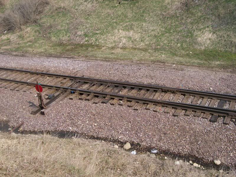
The box mounted on the headblock tie is the point detector. This switch also seems to have a point lock, the blue thing.

Closer view.
I think that track is out of service. I think the blue thing isn’t a point lock but a clamp put there by MOW forces, that’s probably why it’s blue. If you look on the switch stand where the lock goes, there is a tag there. I would bet that the regular switch lock has also been temporarily replaced by one that only MOW has a key to.
Was there any MOW machinery on the track at the time? I know around here when they store machinery on a track, that’s how they protect it. One night we had a bad order engine that had to be set out where the only track was locked out by MOW. They had to get someone out of bed (turned out to be the roadmaster) to come and unlock the switch and take off the clamp.
Jeff
I think there was another reason why it was tagged out.
I don’t remember anything tied up there at that time.
Does this be vallid for the second switch in a crossover to a spur too? Or a derail in this spur? [:)]
Wolfgang
Yes
No
I am not sure I understand the first part, but here goes.
Point detectors will be placed on:
- The turnout that leaves the main track
- If the turnout leads to a another turnout in a parallel track to the main track, forming a crossover, that turnout will also receive a point detector (because crossover turnouts must both be normal or both be reverse)
- Depending upon the railroad’s standard practice, derails protecting the turnout to the main track or to a crossover from a parallel lead
- Depending upon the railroad’s standard practice, derails and secondary turnouts in a ladder leading from the main track turnout as well.
To know for sure on any given railroad, I’d need to see the standards for the time in question.
RWM