I’m about to start track laying and wiring on my N scale layout and I’m wondering what the best way is to organize all the wires underneath ones layout. I’m always amazed when I see a power bus or a control panel that is really organized with everything labeled and color-coded. Can any of you pro’s out there can give me some tips? Thanks in advance.
Just a few suggestions from a person who has designed and installed wiring for some really large and complex layouts - and has one under construction right now:
Device and circuit identification: Work out a consistent identification pattern for the things connected to your electrical controls. Example, ‘T(urnout)’ followed by a number for switch machines, ‘S(tructure)’ followed by a number for structure lights, ‘A(nimation)’ and so forth. Identify all of these things on a layout drawing, and on panel track schematics (if used.)
Circuit documentation: Draw up a COMPLETE set of circuit diagrams, label all devices and every wire (Two coil switch machine T6, common wire T6C, “normal” route coil wire T6N, “reverse” route coil wire T6S…) These will be worth their weight in fine diamonds when troubleshooting becomes necessary, IF you do the next thing…
Physically label each device and every wire terminal with the ID’s developed in the steps above. The labels should be clear, and large enough to read easily.
Test every newly-installed wire, switch and/or device IMMEDIATELY. Don’t assume proper operation, test for it.
Avoid quick fixes and unlabeled ‘temporary’ connections. Those temporary connections have a bad habit of becoming permanent - until they cause a problem.
And now, a few suggestions about physical installation:
Don’t try to save wire by running the shortest distance. Gather all your wiring into ‘runs’ and anchor them to the tablework. (During installation, you can hang old-style shower curtain hangers from screweyes and slip your wires into them. Proper cabling can come later.)
Keep everything as accessible as possible. Troubleshooting is a lot easier if your terminals and wire junctions are right on the edge of the layout, so you can work on them while seated in a chair in the
Start with a schematic and organize it on that. Microsoft paint or a similar artsy fartsy program works OK for this. Lay in your track plan first. Lay in all your block feeders followed by turnout control circuits. Signals come next followed by miscellaneous lighting and what not. As you add circuits (wires) to your schematic keep re-arranging them until you have clean flowing lines.
When wiring a layout, I like to use solid core wire for making the runs and switch to stranded where I connect to the track, turnouts, etc (devices). Solid core stays put and won’t tangle like stranded does. Switching to stranded at the devices makes it easy to fish the wire plus eliminates stress on the devices or wire. Solid core is especially nice for buss wires because it is easier to tap and solder to (with stranded as a takeoff). I like to avoid bundling because it can be a pain to trouble shoot.
Beyond multi curcuit cable, polarity, and device grouping, color coding isn’t real practical because there are so many different circuits. You can easily get lost. Phone companies color code and since there are so many circuits, they use stripes in different patterns. It takes a lot of practice for linemen to decipher it all. Tagging has always worked best for me. Label each circuit on your schematic and tag each corresponding wire on your layout. When trouble shooting or making modifications, the tags are easier to recognize and gaurantee you have the right circuit.
Chuck, I didn’t see your post. I didn’t mean to try and rewrite it. We sort of went to the same school I think but you put it in better words than I did.
I am not much of an expert. But I’ll tell you what helps a novice like myself. I use lamp cord. It cost more, but when I split it down the middle, I get twice as much. It’s also very flexible and easy to work with. I crimp spades to the ends and connect everything to barrier terminals from Radio Shack. I find that the 8 position barriers are only a little more than a 4 position. I use the jumpers that are made to fit. (also from radio shack). It makes it a snap to change things around.
Maybe that will help. But I am sure the pro’s on this forum will have a lot better ideas. –
I also label everything - the panel controls, terminal strip connections, wire, and where the feeders pass though the layout top. As all my interlockings are named, I prefer to use names rather then numbers. For example, the turnouts at CP Greg are labeled CPGreg - 1 and CP Greg - 2 and the blocks between CP Greg and CP Haines are labeled Greg - Haines 1 and Greg - Haines 2.
I use homemade terminal strips for the connections behind the control panel and for the turnout and signal connections at the interlockings. I use IDCs and wire nuts to connect the bus wires to the track feeders.
I bundle the wires together with plastic cable clamps attached to the benchwork.
I try to color-code where possible. For my track power bus and feeders, this seems to work pretty well. I use red and black for that. For signals, I’m using red, green and black. For all the miscellaneous other stuff, I’ve got coils of green, yellow and white wire, but I’m not terribly religious about how I use them.
I think it’s a really good idea to use multi-conductor wire for turnouts. I bought rolls of telephone cable, 4-conductor, for all my turnout wiring. It’s a lot neater than using 3 single wires. Another option for turnouts is to run a single “common” wire and daisy-chain all the turnout center-posts, and then you’ll only need 2 wires from the control panel for each turnout.
My layout is a free-standing table, 5x12 feet, on casters so I can move it around the room as necessary. At some point, I may decide to rotate the whole thing so the “front” becomes the “back.” I’ve wired my control panels through a point in the center of the layout so I can remove them from one side and put them on the other. In my case, there are 3 separate panels for turnouts, so I also have the option of putting one “dispatcher” on one side of the layout in an ops session.
This may be stating the obvious but organising your wiring is a mechanical rather than an electrical issue.
So, some mechanics (well practical things at least).
If you have any long runs between the power/switch and the end that does things it is well worth segregating the long runs up to close to where the wires need to go and do their individual things.
As an example… if you have 18’ of layout with the input at one end there is no point in the cables that don’t do anything until 6’ in to be mixed up with the cables that start at once… or the cables that don’t do things until 12’.
If this is on a fixed structure you just make nice long runs, It costs a bit more but if you use multi core cable you cut an 18’ + the run into the control box(es) for the stuff beyond 12’… 12’ for the stuff beyond 6’. Then you extremely carefully open the sheathing in the last 6’ in each case and just take out each wire you want to use as you work back from the far end. This has the advantage that all your wires stay neatly bundled up and that you have an absolute minimum of joints in the wire. Okay, it is a bit of an expensive way of doing it… depends on your budget and how you want to go- time/monet when you build or possible maintenance issues later…
Maybe I should have started with suggesting getting a large reel of multi core (I struck lucky… they ripped a skip load of stage-works out of a job by where I used to live… by the time I stripped off the shielding and armour I had a 40gallon drum stuffed full of grey wrapped 8 core.
My plan is to get heat-shrink colour-coded number tags to identify each 8 core where it starts and anywhere it has a join. (Both sides of join)!
I hope to work out a pattern so that all of the wires in any one 8 core do one job… switch control, power, whatever. Then the collars for the types of run can be coded as those above have sugg
All my wiring is color coded. Color coding is easy once you determine what color will be for what purpose, and be rigid with the color code (ex–all grounds are black, all positive wires are red, and so on) My main track bus is black and white–one for each rail. My turnouts are wired with computer cable (six wires inside, I only use 3) routed through spark plug wire separators hot glued to the benchwork. All others are routed through routing clips screwed to the benchwork. Make the wiring into a “harness” of sorts. Neatness counts.
Wiring diagrams are essential. What you wired today you will forget in a year. Document your wiring as you go. It will save you troubleshooting time down the road.
The best advise i can give when it comes to neat wiring practices is to keep track of your connections/wires hook ups by number. These can then be recorded in a master log book. Believe me when i say that this extra step will save countless hours when troubleshooting! In Addition, i like using terminal strips to connect my wire ends. Besides looking professional, terminal strips are a handy place to change wire size commonly used for track feeders, Aux lights, ETC…
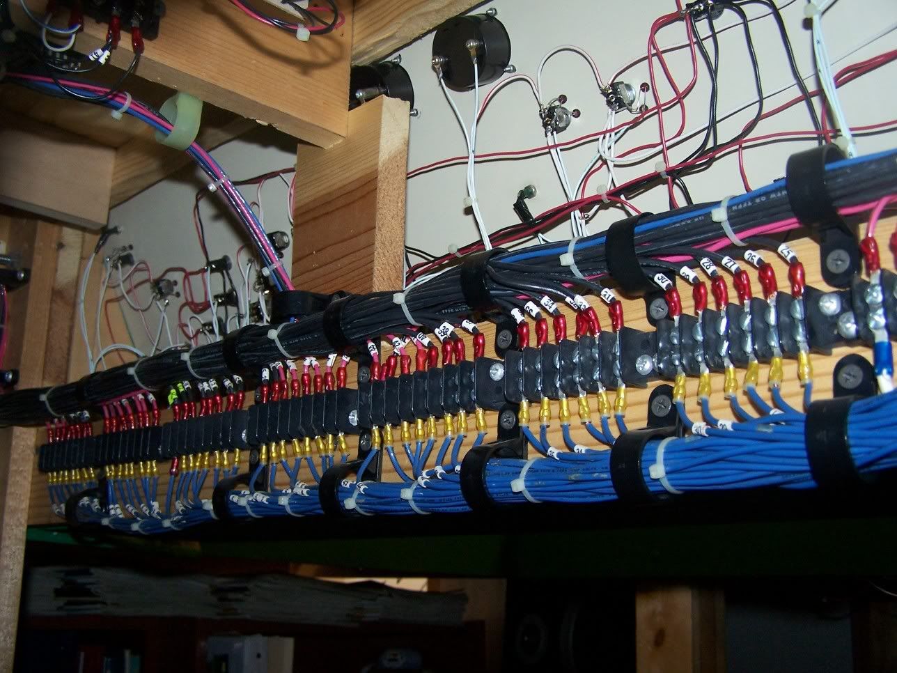
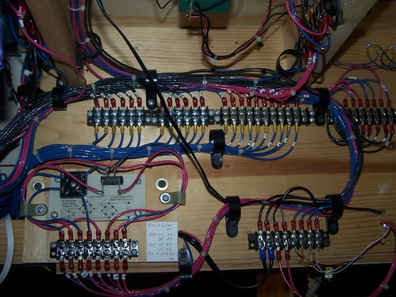
Here are a few pics of my wiring:
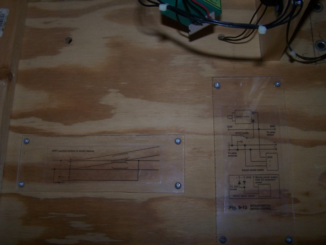
I made these schematics to remember my turnout wiring:
Thanks for the great replies everyone, there’s lots of good info here, keep it coming.
A lot of you have mentioned phone wire and other multi conductor wire, were can I get this stuff and is there such a thing as 3-conductor wire? I don’t want to spend any more than I have to when I finally start wiring so is there a place I can get lots of wire for cheap? Thanks again.
Standard extension cord wire is three-conductor - at least, the present-day ones with three-prong plugs and recepticles are. Only problem is that the green (ground) wire tends to be smaller than the two main conductors. OTOH, the main conductors are grossly oversize for anything lighter than a DCC bus…
Chuck (modeling Central Japan in September, 1964 - with salvaged communications cable)
I’m a television engineer and have a lot of experience running cables.
[list][] Document your runs.
[] Make things as accessible (near the edges) as possible. Long service loops especially for equipment in pull out drawers is very beneficial.
[] Develop a color code and stick with it.
[] ID each cable at each end with a number and destination and purpose. Labels under clear shrink wrap work great (labels that are glued can shed with age and glue sometimes changes and becomes gooey)
[] Label terminal strips
[] Always lay in a few spare runs for future growth and failures.
[] It never hurts to go up a size or two on wire gauge especially when running power in case you expand.
[] Keep power runs separate from signal runs. You should avoid bundling power (especially alternating current ie; 110 volt house electricial) and signal cables together. This will reduce the possibility of hum and induction/interaction between wires.
[] Use zip ties to bundle similar signals but don’t go overboard.
[*] Shorter runs are always preferable especially for power. The longer the run, the higher the resistance/voltage drop and the more chance of generating an unwanted signal that may affect D.C.C. or other wireless devices on your layout or in your home.
[/list]
*The NMRA has a recommended practice. At work, we rely on the resistor code because it is very easy to remember if you memorize this: Bad beer rots our young guts but vodka goes well.
Bad=black=0
Beer=brown=1
Rots=red=2
Our=orange=3
Young=yellow 4
Guts=green=5
But=blue=6
Vodka=violot=7
Goes=gray=8
Well=white=9
The above colors are often used by wire manufactures for the insulation on multi conduct
Between my control panel and the layout was a bundle of 40+ wires, after using zip ties, I used a plastic coil wrap that encases the bundle. It remains flexable, allows access and be removed and replaced and looks very neat. It comes in different diameter ranges. An example of the small diameter is in the pic of the control panel by the blue workbox which is my 120V line in to a lighted switch.
As said before, lable lines, stick with a color code, buy spools of good wire, in the long run its cheaper than reusing old wire, and test each line as it is installed. Take your time. If you don’t have the time to do it right, do you have the time to do it twice.