Not all cars had pantographs but had traction motors. If it is horizontal and a couple of feet wide it transferred power to the non pantograph equipped cars. It was spring loaded to maintain contact.
Bus bars were quite uncommon in North American electrifications. I believe that the GN box-cab electrics were equipped with them but I’m not sure of any others.
Almost all EMUs today have some kind of connection to their married pair. A lot of time it is just a cable but still provides power to the no PAN other car . That limits the number of pantographs contacting the CAT. Understand that some CAT gets too much oscillation of the wire ? The MNRR M-8s are one example although it is receiving 25 single units at the end of MNRR’s order.
You may have answered something I’ve been wondering about. I’ve frequently seen pictures of MU’s where both units have pantographs but only one is up, and it seemed to me that if both were up, the current on each would be less rather than having one contact carrying the full load. But if the first one causes the wire to oscillate, will the second one tend to bounce and/or lose contact with the wire?
Yes, and if anyone remembers high-speed Silverliner operation in the mid-1970s they’ll remember the amazing spark shows. I’ve never looked at this carefully from the ‘electrical’ side, but it’s quite possible that if the cat’s going to dance and the pans are going to spark “no matter what”, it might make sense to have as many pans sharing the current as possible… even if that made the sparking marginally worse.
Conversely, since each pan will push against and mechanically wear (friction, etc.) both itself and the wire about the same respective amounts - regardless of the amount of current each is carrying - that would be a disincentive to using any more pans than are required by the electrical current flow and resistance, etc. considerations. For example: Why use 4 pans when 1 will do, from that standpoint ?
My understanding is that the old technology (like 1920s) was to have motor generators in the engines. Collect ac and covert it to dc in the engine. It was imperative to always have contact with the wire otherwise the motor could get out of phase when not in contact damaging the engine so they were run all pans up to keep contact with the wire.
This is a major problem with the PRR / Reading type variable tension CAT. This is one important reason to convert higher speed tracks to constant tension CAT (often ignored by constant tension installation critics). If anyone remembers the videos of the 160+ MPH test of ACELAs on the NEC sparking on the PRR cat was sometimes quite a show. Anyone with a link ? Suspect this is one reason for the fall tests during periods of mild temperatures. During the Penn Central (PC) era sparking was so bad on the NEC that is would cause VHF radios to receive the EM that sounded like a unshielded welder being used. Unknown what effect on AM radios.
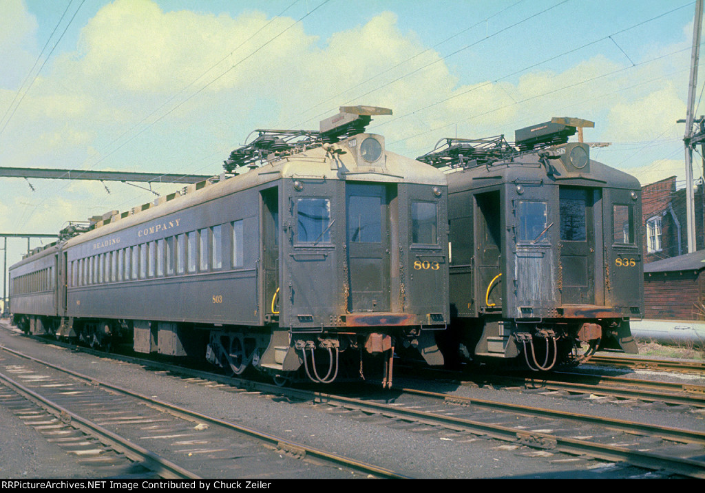
From the paperback book Electric Trains to Reading Terminal by Wes Coates, published by Railroad Avenue Enterprises, Inc., Flanders, NJ, copyright 1990:
“A noticeable feature of the equipment was the pantograph bus connector on the roof of the multiple unit coach at each end. Equipping with a common power bus allowed a train to operate with only one pantograph in contact with the catenary. This reduced wear on both the trolley and the pantograph shoes. It also stabilized catenary voltage on long trains when more than one pantograph was raised, and in the event of damage to the catenary, involving pantographs, permitted other undamaged pantographs to be used for the train to continue to its final terminal. Roof bus connectors had been previously used in Europe, but the Reading became the first electric railroad in the United States to use this type of apparatus on MU passenger equipment.” (pg. 24, middle column)
“A single shoe type pantograph, with steel contact strips, was used to collect power. The Reading would avoid greasing contact wires since steam locomotives would be operating under the catenary wires. The roof-top bus connectors allowed train operation with only one pantograph raised, saving on pantograph and trolley wear, but on longer trains two pantographs would be used. The power bus connectors on the roof of the cars were air activated, so as the train line air hoses were connected and cut in, the contact shoes would be extended to make a connection with adjoining cars.” (pg. 25, left column)
The description and tabulation of the equipment on pages 23 - 35 indicates that were approx. 70 to 100 cars of various types with motors (1 truck only, under the pantograph), and about 20 trailer coaches. The trailers were unpowered (though 1, #799, a combination/ RPO, did have a pantograph), but all did have the rooftop
I lived about 150 ft. from the electrified ex-PRR Main Line between Paoli and Malvern (Philadelphia to Harrisburg, PA) from June 1977 to March 1978, and about 1/4 mile from the Paoli station until August 1980, in the early days of ConRail. Despite many types of electric equipment running past - SEPTA’s ex-PRR commuter MU cars, GG1’s, E44’s, whatever Amtrak had as well, etc. - I don’t recall any interference with KYW-AM 1060, the Philly “all news, all the time” station (someone else will have to explain why it’s a “K” call letter, not a “W”), nor a couple of music stations (WFIL 560, and WIBG, can’t remember the frequency back then). I was a heavy user (esp. early morning hours) of KYW for weather and traffic, but don’t remember any electronic interference, either on the little portable radio in our bathroom or on the car radio, either, and I probably would have noticed and figured out that correlation. (The tracks were just beyond our backyard at the Malvern house, and I do remember a spectacular electrical light show when a heavy WB freight struggled by after a freezing rain one Friday night in January, I think - equal to any fireworks display - but I’m sure I wasn’t listening to any radio then, either.)
Paul, as I recall the custom of using “K” west of the Mississippi and “W” to the east wasn’t started until after several stations started broadcasting, hence KDKA in Pittsburg (which I believe was the first in the country) and WOAI in San Antonio. By the way, I’m not that old; I recall reading that.
The Elgin Aurora and Chicago ( later the Chicago Aurora and Elgin) began operations in 1902. It’s cars were equipped with bus jumpers, admittedly hand connected. This was to bridge third rail gaps at grade crossings. This far predates the Reading electrification negating the claim that the Reading was the first to use this feature in America.
From 1902 to 1928 (design) or 1931 (operation) is a long time, and a lot of technology evolved during then. Would at least a few other railroads/ interurbans/ trolley lines have done the same, or something similar ?
http://www.greatthirdrail.org/rollingstock/index.html Photos can be found at (let’s see if I can get the link to be live as the mobile version doesn’t have the HTML tags available) . The sockets above the train doors are for the bus jumpers. CA&E cars were equipped with them from the beginning and included #460 ( St. Louis 1945) considered by many to be the last conventional Interurban delivered in North America. The freight locomotives were also so equipped with the bus jumpr sockets just above the couplers. The CA&E was rather unique in being almost 100% third rail with only short sections of overhead current collection (primarily street running). I’m not aware of any other interurbans using these but I’m not saying there wasn’t. A candidate would have been the Lackawanna and Wyoming Valley Railroad which was also primarily 3rd rail. I don’t see any evidence of bus jumpers on their rolling stock. Anyone know for sure? We still use the bus jumpers on our restored CA&E equipment at IRM. (We have 8 operable cars, 4 steel and 4 wood. The wood group includes 36 one of the original 1902 cars which I spent quite a bit of time stripping and repainting). Hope this helps.
The old Reading MUs, as well as the PRR MUs and PRR designed Locomotives were all AC. The speed was controlled by changing the secondary tap on the transformer.
I gather that these bus jumpers were essentially just cables, that had to be manually plugged-in / connected and disconnected ? I don’t see any similar bus bar over the tops of the doors or on the roof. Here are a couple links to more photos of it (neither are mine) to compare and contrast:
The difference with the Reading cars is that the bus bar connection was automatic - no wires to be plugged in, it just happened when the train line air system was charged. Also, it was a large flat ‘bar’ or ‘horn’ shape, kind of like a pantograph on its side, not wires. So while the bus connection concept may not have been an original idea, implementing it by using the overhead bus bar and automatic connection/ disconnection feature appears to be a unique advance in the U.S. at the time by the Reading RR.
Paul North.
P.S. (early Tues. 30 Sept. AM): While 600 volts DC live would lend itself to being connected by mere wires, the 11,000 volts AC of the Reading’s electrification would be a lot safer with the ‘untouched by human hands’ nature of that automatic bus bar arrangement. - PDN.
My own less than pleasant experience with a 440 volt bus bar suggests that even plugging in a bus line into a live 600 volt line would be quite hazardous to the carman stuck with the task.
William D. Middleton’s classic book When the Steam Railroads Electrified (kalmbach, early 1970’s) shows and mentioned the Reading’s bus bars twice - once in the text, and once in a photo caption (in the chapter entitled “Electrifying the 5:15”).
He also included a couple photos of the GN class Y-1 box cab electric motors that had them in the chapter entitled “Conquering the Cascades”, but I’m under the impression that not all of the 8 such units did. I can’t recall whether they were mentioned in the text or a caption, either.
Maybe more on Middleton’s comments on these when I have more time. From a brief scan of the book, I did not see any others with the bus bar, and it is not mentioned in the appendices on the technologies of electrification.
Ironically, when the GN electrification was shut down and replaced by diesels, the Y-1’s were sold to the PRR - 1 was scrapped/ salvaged for parts, the other 7 went into service, as class FF2. They were mainly used in helper service in eastern Pennsylvania - mostly within a few miles of the Reading MU cars that also had bus bars ! I was not aware of this acquisition, and will take a look at some of my PRR references in the next week or so to see what else they have to add about this transaction (Mike Bezilla’s book, and some color photo books, etc.).