I have one area of my railroad (about 10’ long) where it will be very hard to access the underside of the benchwork once all scenary is in place. So I am trying to do all wiring with the benchwork tilted up. Track feeders, tortoise switch machines and signals are all decided and will be mounted.
The various lights I will need (yard, platforms, etc) is a bit unknown right now so I was thinking I will mount some kind of a barrel connected (female) with 12V supply on the underside, in a 1/4" hole and later on can come in and tap off that barrel connector for lighting.
Has anyone done anything similar? What connector did you end up using?
I was considerign the very thing, they are sturdy and also easy to plug in with one hand (while the other hand holds the structure). If you use stereo ones, you can have 2 independent circuits in one building, say the platform lights vs the interior lights of a station.
I tried the stereo connector many years ago but gave up on them because they short when plugging and unplugging if you forget to turn the power of. I did like Randy’s idea of simple one hand connections. I use micro connectors for everything but houses and my vehicles, they can be a problem connecting them in tight places.
I make my own connectors for my houses and vehicles from K&S brass tubing and brass rods.
That’s why you turn the power off when plugging things in. [:P]
If you don;t need 2 circuits in one structure, you can still use the stereo plugs and jacks, and use only the tip and the outermost ring, skipping the middle ring. No shorting then.
These things are called 1/4" phone jacks. They come in “mono” and “stereo”. You can get shorting or non-shorting. They’ll handle quite a bit of current.
I thought the OP was talking about RJ12 plugs. They doesn’t short. They won’t handle much current, but if you’re only doing a “couple” of LED’s, they might work nicely. And you’ve got 6 wires to work with.
No Randy/ RR_Mel’s interpretation was correct … phone jacks … 1/4" … I thought the shorting issue would be a dealkiller, I surely will not remember to turn off.
But stereo with floating middle would work well. I browsed a lot on allelectronics.com … but one confusion I ended up with is how do I connect wires to these 1/4" connector on the Male side and Female side?
I think I have a lot to go over prior to getting here, but still would like to place an order so materials are here by next weekend when I am back from Europe.
The cap unscrews from the male side and there are solder points in there. The female ones, they come in several varieties, some are just a square box with solder lugs, others are designed to be mounted on a PC board. They usually have a diagram engraved in the plastic showing which terminal is which, if not there are at least numbers by each terminal and the manufacturer’s data sheet would show which terminal is what.
Actuall, if the lighting is LED, telephone-type plugs and jacks would work fine. They aren’t designed to handle high current, but LEDs would be fine. I can see possibilities there as well. 6P6C jacks and plugs give you up to 3 circuits (I wouldn’t use a shared ground with the small wire size), possibly 4 (2 positions combined for the ground, and then 4 other contacts for the hot sides). Not as robust as phone plugs, but it’s not too hard to crimp on another end if one of the plugs breaks. About as easy to plug in, slightly more difficult to remove since you need to press the tab in to release the plug.
Like most things, there are probably a million different ways to do this.
Him has GROUND bus. Him has HOTEL bus. (HOTEL bus/power is 12v + dc from separate transformer with fuse)
Him has building with light. Light has (resistor and) a pair of wires. Drop wires through top of table him does. Him drills hole in fascia, and pulls wires out front where the beese (plural of bus as per LION / SubChat) are.
Is easy. Why LION would een think of spending money on stuff like connectors is beyond him.
Randy even with my 50 years of electronic techie background I rarely remember something as simple as making sure the power is off so I try to always make it idiot proof, me being the Idiot.
When making up micro connectors using socket strip connectors for several years I was polarizing them so “Idiot” couldn’t plug them in backwards. Over time using the NMRA 8 pin DCC connectors and a dob of red paint on the corner next to the red wire I now can use non polarized micro connectors with out screwing up by always aligning the little dots of paint.
Dave you can go berserk with vehicle lighting using the K&S brass connectors. I built up separate flasher circuits for my emergency vehicles and have a separate feed to them so that they flash randomly. I have several extra three circuit road sockets so that I can move them around also.
I standardized on the third contact spacing so that my vehicles with flashing (rotating) beacons can be moved around too.
Mel
Modeling the early to mid 1950s SP in HO scale since 1951
Thanks for the pictures. I think I have already gone nuts with vehicle lighting. I have about 20 HO vehicles with headlights and tail lights, and a couple have working signals and interior lights. Most of them are cars, and I used fiber optics to feed the light to the lenses. Currently they all have a bundle of wires sticking out the bottom which I hadn’t really figured out how to deal with other than drilling relatively large holes everywhere. Even then, I could see that getting them to sit down flat on the road surfaces would be a challenge because of the tension in the wires. Your solution pretty much solves those issues.
To mount the brass connectors I am thinking of using pieces of fiberglass copper coated circuit board glued to the bottom of the cars. That will allow me to solder the brass rods in place which will be a more solid solution than using glue. Clearance may be a problem on the cars with smaller tires but I can always hollow out a bit of the frame to make space.
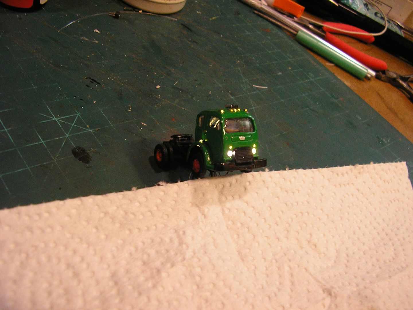
Here are a few of the vehicles that I have installed lighting into:
This one has working signals as well as roof and fender clearance lights. They don’t show up too well in the picture:
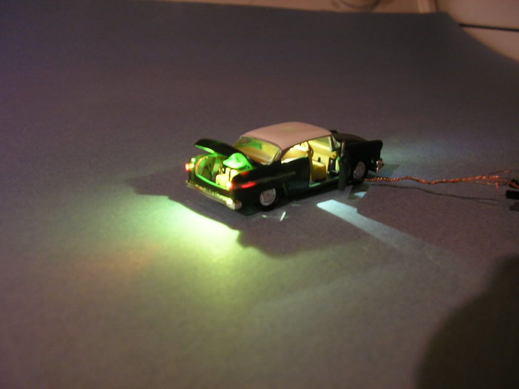
This Dodge has interior and trunk lights. I have to up the resistors a bit to tone the lights down:
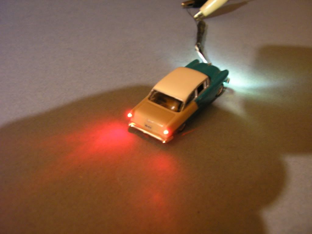
Chevy with brake lights on:
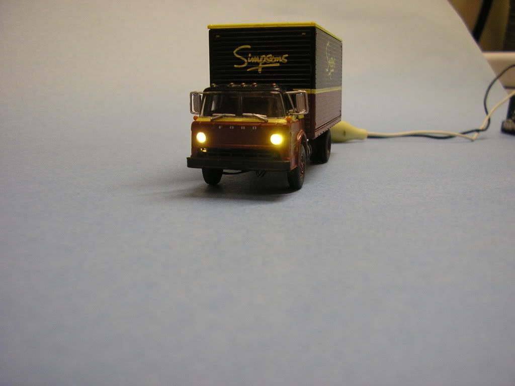
Simpson’s truck. Simpson’s is a long defunct Canadian retailer:
Thanks for your pictures Dave, very slick!!! I went with a pair of 1mm micro bulbs for headlights and a third hidden inside with .030” red fiber optics for the tail lights and yellow fiber for running lights. The micro bulb headlights actually light up the road in front of the vehicle.
I made a 1952 Hudson with car troubles, hood up three guys under the hood. I glued the guys to the car so they go with the car when I move it around.
Mel
Modeling the early to mid 1950s SP in HO scale since 1951
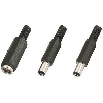
Coaxial connectors. Those are also a good choice, no change of shorting while plugging in or removing them. And also sturdy and robust like phone jacks. Commonly seen on power supplies of all sorts, mainly because they don’t short on insertion or removal.
DIN connectors are larger and the most familiar one is probably the 5 pin one that computer keyboards used before the smaller PS/2 connector and then USB came along, but they came in various configurations. The 5 pin would give you effectively 5 circuits, each pin plus the metal part of the shell as a ground, but they are relatively huge by HO standards and for 1 story structures prohibitively large for N scale. Plug plugging them in and pulling them out requires a good deal of force so if the base is anything but a stuff material such as plywood or hardboard such that the socket side can be securely attached, you run the risk of ripping the socket up when pulling the plug out.


 ?
?