On my Virginian layout I have not decided yet to go with the Micro Engineering bridge the the MRR staff used, another type bridge, or to scratch build my own. In any case, the bridge work will be done at a later time. How do I proceed now to complete laying the rest of my track. Right now there is a gap in the subroadbed where the bridge will go. Do I cut another piece of plywood for a temporary bridge and lay the track across it? With or without cork roadbed? I am using flex track in that area, Do I create joints right at the edges of the bridge so that the track can be removed to put in bridge, or can I remove the temporary plywood bridge and build or install the new bridge under the track while the track remains in place? Also, does the Kalmbach book on bridges and trestles provide any answers to my questions. Thanks for any guidance you can provide.
I guess it depends on how long it will be before you build the “real” bridge, and what your construction methods are. I would put down the temporary plywood bridge, mounted so that it doesn’t need roadbed, and mount the approach tracks so they can be removed, that is, with pins of some sort (foam base) or with tacks or spikes (wood base.) Then, when you’ve got the bridge ready, you can easily take the track up and re-lay it to fit the bridge.
It really helps to actually have the bridge or know the specifications (shoe to shoe length, height from shoes to railhead etc), however you can always improvise at this point. Obviously, working a bridge into the design and trackwork is so much easier on your scenery contours, abutment placement, as you lay the trackwork, you just need to keep these things in mind as not to have so much reworking of the final results. I would first study the various bridges you may eventually use so at least you may have some idea as to the basic length. This will help in basic contour shaping of the scenery for the area. If the bridge is to be straight, a piece of 3/4" pine or ply will suffice for the span. I perfer to use wood risers as the “sub abutments” for bridges. Not sure of your building technique (open grid, plywood decked or foam), how you handle the actual bridge installation will vary due to this. Also much of the clubs layout is flex on 1/4" pine roadbed, this allows me to actually spike the bridge rails well past the abutments to help in anchoring and allowing for track feeders (not rail joiners) to those rails. If you plan on using any sort of open girder bridge/ trestle you should consider using bridge flex track( like ME code 83).
Just lay your track across the supporting wood w/ or w/o roadbed, if you can’t figure the exact abutment positions, the track can be just cut at the time of bridge installation.
I just cut out the rail and roadbed and subroadbed when it’s time to install the bridge. I work so slowly, who knows when that will happen but it takes little effort to do when the time comes. Waiting until you have bridge in hand is good in case you change your mind.
Here I will cut the spline and track out when the time comes.

Here I am hoping to build a big steel bridge and will cut out a four foot section when the time comes. The canyon will go to the floor. My version of the C.P.R.s Stoney Creek Bridge.

Brent[C):-)]
To go along with Mr B’s advice, how much scenery work you plan to do before you do the bridge? I would keep any work 8 inches to a foot or more form your site. That way, when working on the bridge you won’t damage any of your completed scenery. Also, it will make it easier to make changes to the terrain around the site if necessary to get the bridge to look the way you want it to.
As for the track, whether you put it on roadbed or not is up to you. I would suggest cut one piece of flex track to fit the gap, solder two together if over 3’, so that it will be easily removable and one set of feeder wires will keep it powered. Make sure the ends of the track leading to the work area are left loose enough so that you can easily remove the splice track, then install the finish track when the time comes. Be sure to leave some ties out so that you can slide the rail joiners into place to connect the pieces.
Good luck,
Richard
I’ve been trying to address similar issues at an early stage in my cookie cutter layout. You might find some interesting input in the following thread.
http://cs.trains.com/TRCCS/forums/t/203642.aspx
In my case, I am planning a bridge across a straight section of an elevated gap. I wanted to have a complete enough plan so I could cut the plywood appropriately between upper and lower sections, leaving a lower base for the abutments, etc.
In my case, I will have the bridge crossing a lower track so I had to know how to manage the height aspects at the crossing as well as at the bridge abutments, including as you mention where the upper level subroadbed, roadbed, abutment top & shelf reside, etc. Again, in my case, I have selected the bridge (for which I’ve seen 3 length dimensions), and have concluded I’ll be best off building custom abutments to ge the exact heights I want for the bridge shoes and the track heights. That’s because bridge shoe height (vs rail), height of abutment top where approaching ties reside (vs ledge for bridge shoes) to rail height, end of rails (vs bridge, abutment, etc) and in my case grade at the bridge (track will still slope up after the crissover so vertical grade transition to flat occurs away from the bridge) all needs to come together. I ordered the bridge (Central Valley 21" truss) to have it in hand but found enough info to make the cuts, get the grades (and clearances) right and have a complete plan in hand. I ended up having a longer straight run available than I anticipated so will put a 10" girder bridge in series, so there will be an abutment at each end, a pier between the bridges and of course the bridge crossover point above the track below, all 4 points at a slight grade which dictates heights, all from the needed clerarance from the crossover point. A bit complex, but the plan is needed to minimize major adjust
Before I scratch built this bridge. I first had the plywood sub road bed in place, and before I laid the track I cut the roadbed out to the size I needed for the bridge. I then used that part of roadbed to make a template for the size of the bridge. I then put that part of the sub roadbed back on temporary, with no roadbed, and then laid the track. I built the bridge at my work bench.After the bridge deck was done I removed the sub road, and left the track in place with nothing under it. I then put the deck of the bridge in place of the roadbed, and secured the track to it. after that was all in, I then built the bents in place. Hope this helps.
Sam
Thank You for all the suggestions. It sounds like I can create a simple plywood bridge for now with some temporary risers supporting it. If you are familiar with the Virginian project from the magazine, this is the curved bridge on the way up to Green Hill. The bridge will be on an 18 inch radius curve for a length between 18 and 20 inches at a height of about 3.5 inches… David Popp used the Micro Engineering Tall Steel Viaduct bridge (part no. 75-514) for this bridge, but as of the current issue of the magazine and the project layout videos, the bridge has been on backorder so there has been no information about how it was put in.
I will definitely place the bridge before I do any of the scenery on either side or under it. I was not aware of the ME Code 83 Bridge flex track. I have seen pictures of bridge track with guard rails but assumed these were either hand laid or came as part of the bridge. Thanks again, I have lots to think about now.
When I built my layout, I knew where the bridges would be and had a rough idea of how they were going to be built. I used 3/4" plywood for my subroadbed, cutting it into straight strips or curves of various radii, and, because I worked without a track plan, simply placed the curved sections where they needed to be. I used the widest curves which would fit, so most on the main line are 34" or larger. The benchwork is open grid, so risers were added to all of the roadbed, then it was raised as required and fastened in place - this included all areas where bridges were later to be installed.
After the track was in place and fully tested, I stapled aluminum screen over the open areas and added plaster.
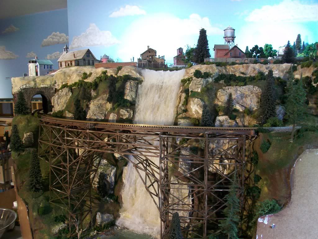
When it came time to add the bridges, I calculated the required length for each, then removed a corresponding length of track in the appropriate area. The plywood subroadbed was also removed, then the bridges shown below were constructed using the upside-down sections of roadbed as patterns: the bridges were built upside-down on the bottom of the removed roadbed. This ensured the proper radii and endpoints.
As I mentioned earlier, I had a rough idea of how they were to be built: what turned out to be roughest, though, was determining where the bottom of the support towers of the taller bridge would be and how much the bottom of each leg would need to be trimmed, as the scenic landforms were already in place. This was a real test in cut-and-fit construction, and while the roadbed track and bridge construction were both efficient and enjoyable, I would not want to repeat the bridge placement in the manner in which it was done. Instead, I’d pre-plan the type of bridge and install flat areas for each support tower’s base during the initial phases of benchwork construction. Tower height could then be measured easily with a ruler, and all legs trimmed to the same length. Both bridges, incidentally, are removea
To bridge or not to bridge, that is the question.
A ‘bridge to the future’ or a ‘bridge to nowhere’ may be a necessary evil.
What, if I may ask, is to stop you from installing the bridge now?
If you insist on a later date for the bridge, I would provide a temporary support and solder in track where it is to go and leave the rail ends right where they need to be to install the bridge later. THEn you just unsolder your track piece and solder in the new bridge when it is ready.
Just my opinion and advice and others may vary.
[8-|]
This ME Steel viaduct was built/ installed much like that of doctorwayne’s. As you see in the pic, the tower heights are rather crucial as ramdom cutting of the height not @ the sections will require modifications to the base crossmember girders.
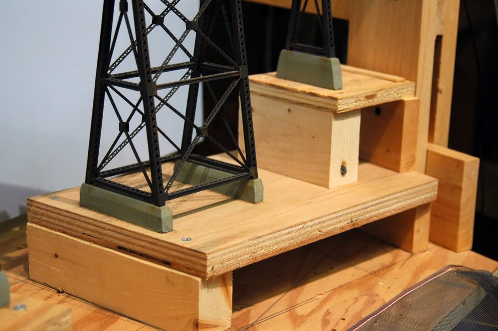
You are using a fairly small radius of the 18". One thing to keep in mind is that tower assys are placed on 30’ open deck girders. The tighter the radius the sharper the mitered angles will be to follow the roadbed template. The 50’ girder clear span is probably the longest section that you will be able to use due to the sharp mitering and greater tie overhangs to bend the curve to install.
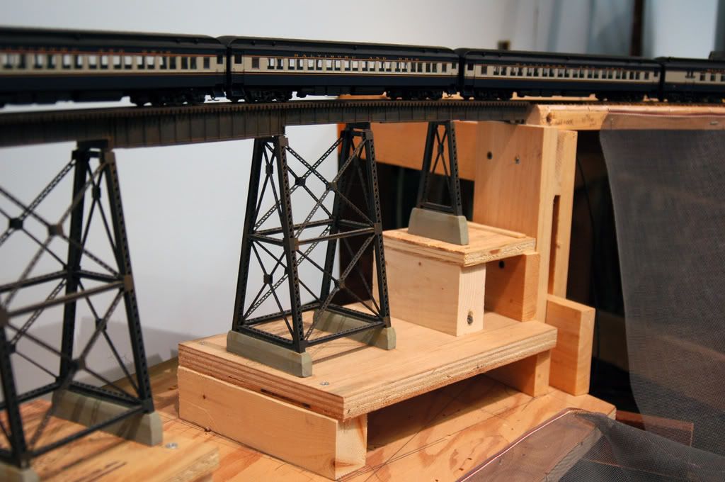
I placed plywood bases @ appropriate height for the tower/ footing assys. Minor adjustments can be made by the height of concrete footings (these were fabricated from soft pine- and sand easily) This bridge is quite secure yet can be removed rather easily. I allowed the track to extend on the ubutment and was able to spike the rails as well as hide the track feeders past the abutments.
LION built a 24" long bridge support that just hung there in mid air. Him never did build a bridge around it. What him did was to take some lengths of sheet metal and bend them into a “J” shape. The short edge of the “J” ran next to the ties and provided stability, while the track rested on the flat edge. Two of these were required for each track one on the right and the other on the left.
I suppose it helps if you have access to a metal brake, as that will make a nice clean shape. If your tools are of the more plebeian sort a vice and a hammer will do it in time.
The supports were quite invisible on the layout and I assumed that I would be able to build a bridge structure around it someday.
On my present layout, the bridge (at Smith-9th Street) is supposed to have a concrete deck across all four tracks, and so I just used a 1/4 inch sheet of hardboard. Four tracks run over this bridge, the outer two use the two Atlas Chord bridges that I already had , the inner two are without superstructure yet, but plastic members will connect the two bridges into one wide bridge which will at least look somewhat like the actual bridge. I will build the Gowanus Canal below this bridge.
ROAR
Thanks for posting that, bogp40. That’s the way I should have done the tower supports for my bridges, before adding the plaster landforms. [banghead]
Wayne
Can anyone tell me what the height of the ME Tall Viaduct bridge would be if using just the top section of the tower.? I’m getting ready to finalize the height of my risers on either side of my bridge and this could be a factor for me.
Thanks, Roger
There are 3 stories to the towers. I don’t have the actual bridge in front of me to measure, however, the ME parts sheet states the complete tower assy is 10" tall.If you are using only the top 1/3 you would end up w/ 3.3" plus 3/4" (the height of the 30’ girder and bridge track). This would equate out to approx 4 1/8", but I would add an additional 3/8- 1/2" for some sort of tower footings. If you use a rough figure of 4 1/2- 4 3/4" you should be OK. It’s better to allow more height than not enough, the difference can be made up in the footing height or shims of some sort.
I would recommend calling ME ( 636 349- 1112 ) as they offer all the various pieces of the tall steel viaduct and every combination of parts to the 150’ or 210’ kits. They are extremely helpful. The 150’ kit has (5) 30’ bridge spans and 2 tower assy. The 210 kit has (3) 50’ and (2) 30’ bridge spans and 2 towers. I don’t know the span you need, but using a tight 18" radius you’re better off building/ mitering the 30’ spans to minimize the tie overhang. Just would look much better.