Why do some plate girder bridges have ballast? That must add a lot of weight to it.
It’s all figured in, during the design of the bridge. If it has ballast, it is a deck-type plate girder bridge. The track is laid in the ballast as it would be on grade.
Some plate girder bridges, the ties act as the deck. Some use timbers, and some have a reinforced concrete deck that is supported by the plate girders.
Not sure of the advantage or the circumstances for one type over the other, I guess it’s all in the design of what the bridge is crossing and the span required.
Maybe a resident civil engineer will chime in.
Mike.
Dissusion here
http://forums.railfan.net/forums.cgi?board=Infrastructure;action=display;num=1111672974
This has ballast. It is NOT a deck-type plate girder bridge:
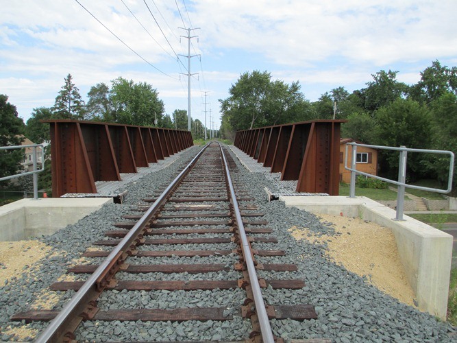
Ed
Any more pictures of that bridge Ed? I would like to see the substructure.
Mike
Yes, Ed’s example is a Through Plate Girder bridge. Some newer truss bridges also have ballasted decks. (Many older trusses cannot accommodate the extra dead load.) In other words, any type of bridge could have a ballasted deck if the design is robust enough.
An open deck is cheaper, often a consideration, but a ballasted deck means the track structure is more uniform, easier to maintain, and the fire hazard is greatly reduced. The deck pan may be concrete or steel. Some wood pile trestles have a deck pan made of wood rather than precast concrete.
John
Nope, especially not of the substructure.
Through-girder bridges are usually used to maximize clearance underneath. When they’re ballasted, they TEND to use floor beams to connect the girders, cover those with steel plate (if necessary) to keep the ballast from falling, and then ballast and track. Sometimes the design of the floor beams is such that they obviate the need for the steel plate.
Here’s another:
http://www.bridgeofweek.com/2015/12/plumas-county-california-bridges-union.html
Ed
OK, so now I know. Just thinking that something is holding the ballast there. I hope the OP’s question is answered !
Mike
http://www.bridgeofweek.com/2015/12/plumas-county-california-bridges-union.html
Scroll down to the second picture. Neat dint in the first gusset on the right! Something whacked it hard enough to bend the gusset out of place and pop some rivets.
Dave
That gusset is often called a “knee brace”. It’s very typical (but not bent) of Through Plate Girder bridges. Occasionally they will be outside the main girder rather than on the inside. Pony trusses will often have them too. I have also seen photos of wood pony trusses with outside knee braces.
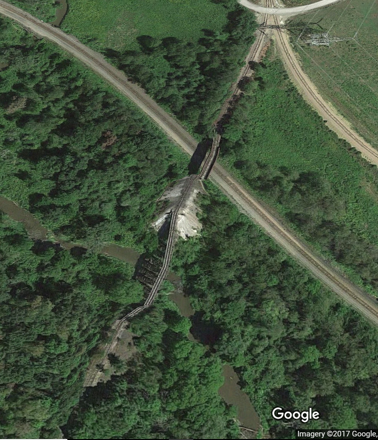
In Charlotte, NC, at the intersection of Interstate 85 and Graham, there is a span of ballasted plate girder bridges that have always been a curiosity to me. This is at the exit for my NC offices, so I see these bridges fairly often.
.
I don’t have a picture of the street level view of the bridges, so I Google-Earthed it.
.
The rails through the bridges are off-center, which I do not understand. The bridges are not wide enough for them to have been double tracked once, and it looks like the tracks are off center by only a couple of feet.
.
I have never seen another single track railroad bridge where the tracks were off center, except in the case where it was originally double tracked and one line was removed.
.
Any ideas? Is this a regular practice? What is the reason?
.

.
-Kevin
.
Kevin, The track is probably off center to allow room for maintenance vehicles. Most railroads have a maintenance road which runs next to the track.
Answer to OP is that bridges with ballast are easier to build and maintain because the ties and rails are not part of the structure. They are just regular track and the bridge just holds the ballast.
Kevin,
As far as I can see, the track is centered on the main part of the bridge–over the roadway. I measured it from the aerial photo. The shadow may give an offset impression.
On the two approach bridges, the track is offset with relationship to the ballast and the “ballast trough”. But it DOES appear to be centered over the girders underneath. For some reason, the trough is not symmetrical over the bridge girders. It doesn’t have to be. But the track is centered on the REAL part of the bridge.
Track doesn’t HAVE to be centered on a bridge. But it always is, in the “best design”, because it is cheaper. And if you ask the people who are paying for the bridge, they will think that is of great significance.
Ed
.
Yeah, if I had known this topic would come up in discussion I would have gotten out of the car and snapped a picture. The tracks are definitely off center, by a visible amount.
.
I will be back in Charlotte in March. I will get a goodf picture at street level then.
.
-Kevin
.
Kevin,
I just spent more time looking at pictures of that bridge, both from overhead and from underneath. Every time I found something that suggested an offset like you’re describing, I always found that it was due to the camera angle. That even applies to my earlier statement about the short approach bridges. I now DO NOT think the concrete deck is offset on the supporting girders. The view I was looking at is not DIRECTLY overhead, and I can see how the elements visually offset at that angle.
I’m NOT saying you’re wrong. Just that it is not evident in the pictures. I suspect the only way you can KNOW that it is offset is by standing on the tracks, and taking some photos down them. Even better, while you’re up there, measure the distance from the girder to the track rail. If they’re different, you’ve GOT IT. You can even say how big the offset is.
I do wonder why you say there’s an offset. What are you looking at that says that to you?
Ed
Google Earth uses some rendering algorithms that can make for some goofy-looking images:
 CN bridge by Edmund, on Flickr
 WLE bridge3 by Edmund, on Flickr
EDIT
So I jumped into street view and looked down the track:
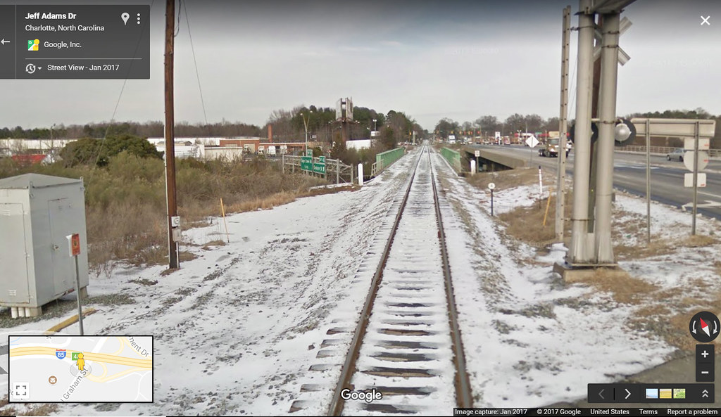 Charlotte by Edmund, on Flickr
Yes, the track looks to be a foot or two off the center line. Aesthetically, it will bug you, like a picture frame that’s crooked on the wall. When they poured the abutments and set the bridge in place the track may have been re-aligned ever so-slightly.
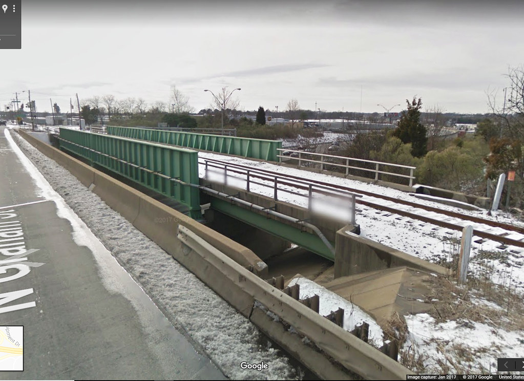 I80Ngraham by Edmund, on Flickr
From an engineering standpoint, NBD. Heck, in Cleveland the super engineers located a new bridge pier a whole two-feet-nine inches off! That’s what you get for $300 million these days.
http://www.cleveland.com/metro/index.ssf/2012/07/pier_for_the_new_inner_belt_br.html
Regards, Ed
Kevin has a winner, here, folks.
(other) Ed’s photo shows a clear offset.
Scaling off the photo, it looks like the “left side” is wider than the “right side” by about 40".
A person could (and does) wonder why.
It looks like the load on the right hand girder has been increased by 15% beyond design (assuming they didn’t actually design to have the offset).
I SURELY do wonder about this one.
Kevin, I have this assignment for you…
Ed
Lone Wolf suggests the offset is to allow space for maintenance equipment. This might make sense, but there doesn’t seem to be a lot of space there, so I don’t know how practical it would be.
It seems more likely that a nearby curve was realigned, and the approaches don’t match up exactly the way they did before the realignment. But that’s just speculation.
Tom
Consider, too, that there is a grade crossing with easy vehicle access at one end of the bridge and a nearby highway and another crossing at the other.
No real need to drive a maintenance vehicle alongside the track with easy access like that. Many of the maintenance trucks today have pretty beefy hi-rail attachments anyway so an access road isn’t always necessary.
Thank You, Ed
That’s a good one Ed. Walsh is currently building the Zoo Interchange project in Milwaukee. I know a few cement finishers from our local that work for them.
What till I run into them again. [(-D]
Mike.