The GG! thread reminded me of a question I have had for years – What is a quill drive and how does it work? Steam and diesel I understand - but I know nothing of electics (Even though I am an electrical engineer by training!)
What are the other types of electric locomotive drive? What advandages did each drive system have? I have seen pictures of box motors with side rods. What did side rods do for an electric.
Side rods allowed one large motor to drive several drivers. The motor sat on the frame and connected to the drivers with rods. Some electrics have one or two motors per axle. The GG1 had two 385 HP motor per axle. These motors were geared directly to the axle.
I’m not clear on quills myself, but I think it goes like this. The locomotive wheels are spoked, and six? seven? eight? of the spokes have some sort of cup on each side that receives the torque from the quill, which has 6 or 7 or 8 arms between the spokes of the wheel. The shaft of the quill is hollow and surrounds the axle, leaving enough room for the axle’s up-and-down movement. The motors drive the gear on the quill and the quill drives the wheels.
See if you can get “The Milwaukee Electrics”, by Noel Holley, on an Interlibrary Loan. It is a terrific book, and Quills are covered in the chapter about the 10 Westinghouse motors that the CMSP&P had.
Quill drives are like previous posters have said a hollow tube surrounding the axle, they are still used today on modern high-speed electric locomotives, and the German ICE 1 and 2 trainsets.
To see what a Quill Drive looks like see this webpage, and scroll down to the section on Quill drives
a quill drive is a form of mechanical transmission that allows the driven shaft lateral movement seperate of the rotation…perfect example is a drillpress…the quill allows the chuck to move up and down while still spinning…
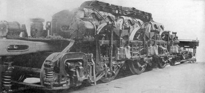
these are the traction motors on a MILW EP-3 electric…the three humps are the motors which are geared thru a quill to the axles they surround
OK, I think I get it. The quill itself is the hollow tube surrounding the axle, driven by the motor. I guess it is called that because it is like the hollow quill of a bird feather. The purpose of the quill is to allow the axle to move relative to the quill tube and the motor so that the axle does not bear the brunt of the motor as unsprung weight.
The part that I am still not clear on is how the quill transmits torque to the axle – the picture of the ADTranz unit helps, but I suppose there have to be some flexible bushings. I read in a railroad history book that the GG1 used spring-like spokes to connect the quill to the axle.
correct on the GG1…if you zoom the pic in my last post youll see the springs on the drivers…most units seem to be unique in each drive…i know some NH electrics use a flexible shaft like a dremel tool…some units the axle itself is the armiture shaft with windings and commutator and the magnents surrounding it meaning no gears at all…and im far from an expert…just throwing guesses and what ive read
In older electrics they used coil springs connecting spokes on the quill shaft to either the spoked wheels or to flanges on the back side wheels. On newer electrics they replace the springs with resilient rubber bushings.
Many thanks to all who took the time to post excellent information. Looks to me like the quill drive was an elegant solution to the problem of mating an electric traction motor to drive axles when the motor (or motors) is too large for the between axle mounting commonly used on diesel-electics while preserving needed lateral motion capabilities. It is also a good way to reduce unsprung weight hence the modern usage.
Did any diesel-electricss use the quill drive? I presume most early diesel-mechanicals used a conventional truck type drive shaft with planetary to the drive axle.
Quill drive would have been an unnecessary complication since the traction motors on early diesels were low horsepower. Nose-mounted traction motors on diesel-electrics have been the norm with the possible exception of such designs as the GA8.
Gereral Electric named them the Bipolar gearless type, and the name stuck. It was a name used from coast to coast. The people who ran them used it, and so did the people who had no idea where they ran
These locomotives were called Bipolar, because each traction motor had only two poles. These field poles were mounted directly on the locomotive chasis beside each axel. They were gearless, because instead of using high-speed motors turning gears on axels, they had low-speed motors with the motor armatures mounted directly on the axels. These features made for a unique and silent locomotive. Since the motor speed was only 458 rpm at 60 mph, there was no traction motor whine, and since there were no gears, there was no gear tooth growl either.
The armature was built on the axle proper (no quill,) and was unsprung weight.
The two field poles (hence bipolar) were mounted on the locomotive frame, and were sprung weight. The sides facing the armatures were flat, since the axles were free to move vertically between them.
So the answer is, each bipolar traction motor was both sprung and unsprung. An elegant, but torque-limiting, solution.