I was very fortunate to be assigned to the radial truck development team within the Truck Development Group in 1982 at EMD. I had spent the previous 9 years of my career there working on noise control projects culminating the introduction of exhaust silencers and quiet fans in response to the EPA noise regs that became effective the first of 1980. Mechanical/structural design was my expertise and I fit well into the team taking the design lead.
Radial steering trucks got a lot of attention in the rail industry globally in the 1970’s, particularly for freight cars. Scheffel in South Africa and List in the US were prominent designs with use in fleets with the Barber-Scheffel and Dresser DR-1 (subsequently AR-1 after ASF bought out Dresser) trucks, respectively. EMD recognized that radial steering trucks on locomotives could be very beneficial with advantages of:
Reduced wheel flange and rail gauge face wear (locomotive trucks were projected to cause perhaps 20% of the rail wear based on numbers of wheels consumed),
Improved adhesion in curves (conventional 3 axle trucks were known to lose about 10% of their adhesion in 10 degree curves),
-Reduce wheel squeal in curves.
In the late 1970’s EMD started seriously studying radial trucks beginning with literature study and the creation of math models to evaluate truck curving and adhesion performance. EMD had hired a brilliant mathmetical mind in Dr. Mostafa Rassaian and he and Karl Smith, who went on to become Direct of Engineering at EMD, worked on these math models on a part time basis until there was confidence that the models reasonably predicted truck curving performance based on EMD’s extensive test data from instrumented wheelsets. Karl moved on to lead other truck projects and in 1982 I joined with Mostafa to start developing truck concepts that had the freedom of axle movement to allow radial steering that were evaluated using the math models. We had about 10 design concepts schematically built that we
One question in regards to loss of adhesion in curves: Is this due to the tractive forces from the end axles being at a significant angle from the rail?
Erik, When you examine how a truck goes thru curves, the trailing axle within each truck generally assumes close to a radial orientation to the curve and the axle(s) ahead of it have an angle of attack wherein the outer wheel is grinding against the flange. On a 3-axle truck due to the long wheelbase, the leading axle is at an angle of about 1.2 deg relative to radial line. So there is lateral slippage at the contact patch with the rail that takes away force that could be tangential to the rail where it is does the tractive work. Of course, that’s a simplification but the lead outer wheel always has the greatest “angle of attack” to the rail is trying to climb it.
Makes sense and thanks for the detailed explanation. I’d also imagine the angle of attack would also contribute to rail wear.
Model Railroader had an article on grades in issue from 1968, and the effect of curves on train resistance has intrigued me since. Specifically how much was due to the wheels slipping against each other and how much was drag from the forces pulling the wheels towards the center of the curve. Most of the texts on calculating train from years ago tend to punt on the “true cause”. Figure this is sort of the flip side of adhesion versus curvature.
I am watching this with considerable interest, and hope it turns into thread of the year…
Keep in mind that the dynamics are very different for powered wheels vs. trailing wheels being steered indirectly from carbody ‘guidance’ (including “Talgo-style” truck arrangements or Jacobs articulation).
I believe Mr. Goding has already discussed this in some respects; as I recall it was brought up in Wickens from ‘the opposite perspective’ regarding wheelset stability in unpowered trailing vehicles. I look forward to seeing a full discussion.
I would expect that there are differences between powered and unpowered steered axles, with tractive forces being the opposite sign from drag forces as well as being MUCH larger magnitude when not braking.
There are also effects on the coned-tread-wheel and railhead interaction, and on the way the axles try to ‘steer’ the truck frame.
This is in part inherent in Mr. Goding’s description of how the trailing axle of a powered C truck is the only one that experiences ‘radial’ centering. You can easily model some of the force couples that the leading and center tread, fillet, and flange face experience when this is true on a pin-guided truck with three motors independently pulling (at what can inherently be three slightly different resultant speeds for a given common admitted voltage, but will not be different for an early EMD single-inverter-per-truck AC drive).
The role of the geometry involved is also important, both for the pivoted and semi-attached ‘centerless’ styles of truck rotation accommodation. As a comparison, look at the American Arch ‘articulated’ truck frame as seen on the early Woodard Super-Power engines. Here the rear wheelset (especially when fitted with a booster) was supposed to take up a radial position relative to the track – but the front articulation pivot location and the need for proper weight distribution make the subsequent location of the leading wheelset geometrically improper for proper Bissel steering of a two-axle truck that is providing active guiding for the chassis. The ‘solution’ circa 1927 was to float that axle with minimal lateral ‘friction’ restoring force between it and the truck frame, but still with full springborne weight transfer to the equalization – this was done with a pair of hardened steel rollers acting on hardened bearing surfaces. Now, since this was an idler axle, there was no particular need to steer it radially, but it would ‘theoretically’ be possible to use Cartazzi-style curvature of the guide plates in the pedestals so the axle would ‘float’ in radial alignment with the effective forward pivot point of the articulated tr
Bear in mind that the single inverter per truck guarantees the traction motors will have the same synchronous rpm’s, but the the torque produced from each motor will be proportional to the difference between synchronous speed and actual speed. This is why you need to keep wheel diameters close to equal on such locomotives, but it isn’t as critical as on a K-M hydraulic.
Another truck/bogie related question is the effect of articulated trucks found on a lot of pre-WW2 electrics and Centipedes.
Do you know how much EMD were involved (if at all) in the radial trucks built by EMD’s Australian associate Clyde Engineering (later EDI and later still Downer and now Progress Rail)?
There were two designs:
The first, applied to standard gauge GT46C units and 1067mm gauge JT42C units from 1998, used swing arm supported axleboxes not seen on USA designs of radial truck.
The second truck design a year or so later had the same swing arm layout on the outer axles but the middle axle had the swing arm replaced by a wing type axlebox with helical springs each side. This was only used on the 1067mm gauge GT42CU-AC, but this has been one of the most successful units ever built in Australia with around 250 units in service.
Both these designs had traction forces taken by traction rods at axle level connected to a floating transom between the outer axles that connected to the truck frame and the rods connected to brackets fixed on the frame edge close to the truck centre.
Another question is Why did the EMD built radial trucks on the JT42CWM (Class 66) look so different from the domestic designs on the SD70 or example?
Peter, The Clyde/EDI design was based on the EMD HTCR but they chose to implement the concept a bit differently to meet the Australian requirements. We didn’t have any direct input on their design from LaGrange.
The Class 66 design was done by a different group of engineers at EMD as I was in the Systems Engineering group at the time doing the mechanical design of the DE/DM30AC we built for Long Island RR (let the flaming begin). The British clearance diagram prevented the use of standard EMD outboard cylinders for the air brake so a new design of the brake rigging was required. Rather than choose to design a conventional cast frame using box sections, enccouraged by the casting supplier, they thought that they cou
I’ll continue on with the radial truck development program again.
Using what we learned about truck yawing under high tractive effort, we concluded our problem of the truck design was that we were using a centerbearing for the truck pivot which offered no restoring force that would straighten the truck upon leaving a curve and hold it straight on tangent track. The simple solution was to go bolsterless, as many truck designs such as the AEM-7’s we were still building at EMD and the Dofasco Hi-Ad trucks used. So I chose to design a bolsterless truck using coil springs (Flexicoils) for yaw stiffness. To support the carbody weight of about 110,000 lbs. required a triple coil spring of 12.5" dia and 24" height which had a lateral stiffness where it would work. A new frame design was required to pocket these springs at the sideframe-transom junctions. We didn’t want to invest the $250K+ we’d have to spend for patterns and coreboxes to make a cast frame so I designed and drafted a fabricated frame that would be suitable for testing without worrying so much about fatigue strength any truck design requires since this would be for test and only had to last 6 months or less.
A major shortcoming of the GP swinghanger truck (Blomberg) has always been its weightshift performance. At a locomotive adhesion level of 25%. the lead axle on the lead truck unloads to 84% of its static weight and the trailing axle of the trailing truck is overloaded to 116% of static. High traction truck designs such as the HT-C had it’s lead axle at 93% under the same adhesion level and we wanted to get similar improvement on any new design. In a two axle truck with motors facing the center, it’s necessary to allow the truck relative freedom to pitch in response to the opposing vertical forces the two nose links impart to the frame. This requires that the tractive effort transfer between the truck frame and underframe take place as close to rail height as possible. The Dofasco ZWT and EMD HT-B acc
Dave, thanks for another interesting and imformative post! Glad to hear the two axle truck performed to expectations. The lack of hunting at 90MPH was impressive, though wonder if it would hold up with worn wheels - this is from reading about Nystrom’s work with high speed passenger car trucks for the Milwaukee Road.
Erik, You are correct that hunting threshold speed is a function of wheel-rail effective conicity which is a function of wear. A new 1:20 wheel profile might be about 1:10 effective conicity due to the way it meets the rail head so depends on rail profile as well as wheel profile. We tested with a fairly new 1:20 profile on the wheels so the 90+ mph stable speed we observed will come down as the wheels wear. Worn wheels wear to about 1:6-1:4 effective conicity on worn rail; that would have dropped stable speed to about 80 mph still above our design goal of 75 mph. Radial trucks that are self-steering such as the EMD designs intended for 10+ deg curves were not designed for service above 75 mph - higher speed radial trucks would not have nearly as much wheelset yaw travel as the steering beam configuration allows (about +/- 1 deg); as with most things there are always compromises to make. European designs for medium speeds above 90 mph typically allow axle yaw only thru deflection of rubber traction rod bushings or rubber chevron springs in the range of +/- 1/4 deg.
I didn’t mention a few things we did with the steering beams in the 2-axle prototype design but they are shown in the patent. We added rubber bumpers on the steering beams that engage mating surfaces on the truck frame after some free travel the amount of which we experimented on during the testing finally settling on 1/8" at each bumper. We also changed the connection between steering beams to be a single stiff rubber bushing. This adds axle yaw stiffness and adds a restoring force to center the axles within the frame. This enhances hunting stability as well.
It was a difficult contract with no time to prototype a locomotive, the 400 page RR spec required a completely new design with no commonality to anything we were building then, we had RR consultants overseen by MTA consultants dictating how we designed the locomotive. The RR spec’ed systems for train control, communication, station identification, anti-lock brakes and along with the EM2000, Siemens AC traction computer and air brake computer made 7 computers talking to each other which was a first for us and took a while to get right. There was also fatigue cracking in skids the engine-alternator were mounted (never done on an EMD loco before) and other teething issues that resulted in us sending all units to Altoona where mod work was done. I’ll suffice it to say the LIRR workforce took full avantage of any issues that came up. So the locomotives got a lot of NY bad press and derision by riders and railfans there. It was such a bad experience for EMD that our General Manager said we would never build another passenger locomotive and we dropped out of bidding for the Metra locomotives that MPI eventually got.
Great thread Bogie_Engineer! It’s always a pleasure to get this info from those directly involved. I just learned more in your thread about dynamics than all of my high school teachers who taught this very subject!
When we got back from the successful 2-axle radial truck test, we immediately started to brainstorm how we could do a 3-axle truck. After much discussion, we settled on an arrangement that retained the steering beams for axle location and yaw freedom, along with an inter-connecting link running across the top of the middle traction motor. The rubber bumpers limiting steering beam rotation and thus axle yaw were retained. We looked at using bellcranks, as GE eventually did on their steerable truck to avoid EMD’s patents, but rejected them due to the difficulty cross-linking them and the greater number of pivot bearings adding cost.
Although it would have been simpler to use a motor arrangement like the SD Flexicoil truck where the outer motors face inward, we kept the HT-C arrangement for its superior weight shift - at 25% adhesion, the lightest axle on the SD Flexicoil truck is at only 78% of its static load, whereas, on the HT-C and now the HTCR, it’s at 93%. We knew we needed to retain the feature of truck yaw stiffness to keep the truck tracking straight on tangent, yet needed the high compression stiffness of the secondary springs to keep the truck from pitching to get the minimum weight shift. That led to the tall rubber springs that shear about 8 inches at full truck rotation, not unlike the Dofasco Hi-Ad truck. Round springs gave us a relatively soft lateral stifffness for good ride and soft rotational stiffness necessary for good curving. With this direct support between truck frame and underframe, no bolster is needed, however, a means for transfering the tractive effort of the truck to the underframe is required. This was accomplished with a four bar link arrangement connecting the first transom thru traction rods to a pivot block that rotates about a post extending down from the underframe and is detailed in the patent referenced below. Elimination of the bolster opened the space for th
Thanks for the post and particularly the link to the patent and the drawings.
One of the differences from the Australian trucks was the flexible link to the centre pivot which was quite different.
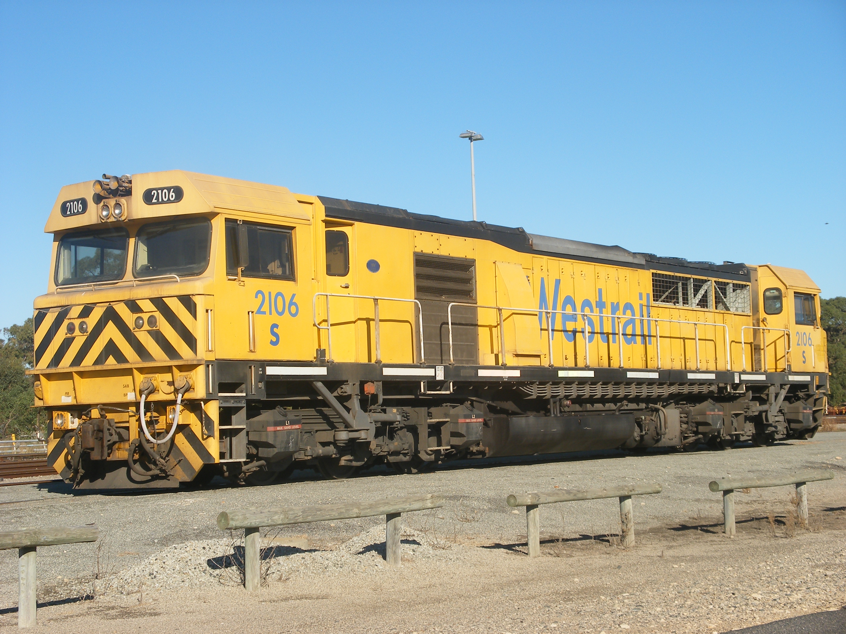
In the Clyde/Downer design, the truck centre pin was located by the external brackets and links to a transverse beam seen in the photo of the narrow gauge version on S 2106 illustrated here. The standard gauge locomotives of classes Q, FQ and V had generally similar arrangement, as did the fairly successful narrow gauge GT42CU-AC of which 250 or so have been built, the most successful cape gauge locomotive ever built in Australia.
All these trucks used the four rubber/metal secondary suspension pads as shown on the EMD patent. I think the MLW/ Dofasco truck was the first to use these pads in 1967, but now both EMD and GE use these pads.
Downer changed to the EMD design of centre pivot link as shown in the patent with the GT46C-ACe which was basically an SD70 ACe squeezed into the Australian clearance gauge.
While not as clear as the S class photo, it can be seen that the external brackets and links are not present on the TT.
Downer indicated that the GT46C-ACe trucks were not strictly steering trucks since there was no steering linkage, but since similar bearing and motor mountings were used, the axles were free to take up radial locations in curves.
I was fortunate to be in Melbourne when the first GT46C-ACe units made their first run in service.
I turned up along with quite a crowd, including engineers from EMD, who I asked about the new trucks. I was quite surprised to be told that no instrumented tests had been performed, but they had run high speed test runs th