Hi everyone, looking for some input on a trestle I’m starting to work on. This trestle is a jv models curved trestle 2016 which can span 36inches and can have bents 18 inches. Could be me just complicating things but its been a real chore figuring out the terrain to trestle connections. I’ve been a bit leary even starting this but went ahead and got a styrene jig made up so getting the longest bents built. The deck rails that I will need is the other issue which I’m troubled with, how do those of you’s that have made bridges curved or straight deal with the rail on the stringers? I really hate the idea of buying single rails and trying to nail them down or glue them down and at the same time have the guage correct. All my calculations for bent footings upto the rail needs to be in place before I can proceed with mounting the bents and filling in the scenery.
Laying track on a bridge is one of those tasks that can sound worse than it actually is.
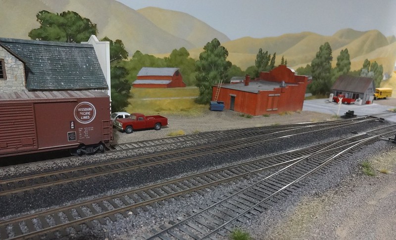
This in-progress scene shows rail spiked to wood ties on a deck girder bridge, but the process is similar for any bridge or trestle with wood ties. The process I used here is as follows:
Measure the rail spacing using an NMRA gauge so the ties will be centered. Mark lightly as needed with a pencil.
Using a pin vise, drill holes a maximum of about every two inches for Micro Engineering small or micro spikes on either side of one rail, spiking as you go. Pre-drilling protects the ties from splitting. Flexible CA like Poly Zap or Microbond can help to keep spikes from working back out of the holes.
After one rail is down, use the gauge to locate the other rail and repeat drilling and spiking on that side.
You can install rail onto the bridge before it’s added to the layout, or install later as I did here.
A rail joint right at the end of a bridge is an invitation for bumps or other misalignment in the track. If possible, extend the rails several inches to either side. You can spike onto wood ties or just keep flex track ties in place, removing the plastic ties only across the bridge itself. On the pictured installation, the rails are contiguous with flex track that extends for some distance from the bridge.
Thanks Rob for your excellent input. You gave me a thought and a need to ask the question, has anyone ever used the regular flex track on a bridge or trestle as is or taken the plastic ties out and replace with wooden ties by removing say two plastic ties and replace with wooden? Also wondering is it the same 3 foot rail in a new section if flex track as what I would receive if I were to order the individual rails from somewhere? Thanks
I’ve blown up this photo as it shows Peco Code 100 flex track laid straight on to a scratch built trestle by my late friend Hans Hubner. It may be hard to see but he used track nails on about every 11th sleeper but I’m not sure if he used any adhesive as well. BTW, this trestle curve would be about an eighteen inch radius.
Cheers, the Bear.
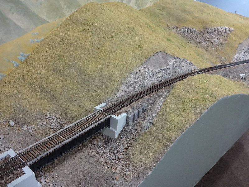
Don’t build the bents to fit the terrain; rather, build the terrain to fit the bents. In other words, build the bridge first, with an idea of where the terrain will meet the bottom of the bents. Once this is done, then build an open frame that will eventually support the structure and scenery. Place the trestle in its location and build up to the base of the bents with wooden piers. If you’re going to have the bents set atop foundations, don’t forget to add these before building up the support structure under the trestle. For the final piece that will actually sit directly under the bents or the foundations for the bents, I use a rectangular block. This block is cut so that it sets about 1/4th inch below the bents without touching them. Then I take this block and draw a diagonal line along the long dimension of the block that has one end 3/8th s higher than the other. Once I have drawn this line, I saw along the line so I get two blocks that when fit back together will slide along each sawn edge making the rectangular blocks into adjustable parallels. This is how you can make the final adjustment to the risers and precisely meet the bottom of the bents.
Once you have the bridge in place and supported by the piers, remove the trestle and add and complete the scenery where the trestle will be located, being sure not to get any scenery atop the support piers as this would shim-up your trestle and throw everything off.
Notes: For some reason, on model railroads, the bent uprights always seem to be built from milled lumber, square in shape (this is what Campbell’s provides in their trestle kits). Where I live the bent u
Thanks JaBear for the great photo, two thumbs up to your friends work. So are you telling me the track is actually Peco flex track off the shelf and not individually placed wooded ties then single rails spiked down to the ties?
Don’t build the bents to fit the terrain; rather, build the terrain to fit the bents. In other words, build the bridge first, with an idea of where the terrain will meet the bottom of the bents. Once this is done, then build an open frame that will eventually support the structure and scenery. Place the trestle in its location and build up to the base of the bents with wooden piers. If you’re going to have the bents set atop foundations, don’t forget to add these before building up the support structure under the trestle. For the final piece that will actually sit directly under the bents or the foundations for the bents, I use a rectangular block. This block is cut so that it sets about 1/4th inch below the bents without touching them. Then I take this block and draw a diagonal line along the long dimension of the block that has one end 3/8th s higher than the other. Once I have drawn this line, I saw along the line so I get two blocks that when fit back together will slide along each sawn edge making the rectangular blocks into adjustable parallels. This is how you can make the final adjustment to the risers and precisely meet the bottom of the bents.
Once you have the bridge in place and supported by the piers, remove the trestle and add and complete the scenery where the trestle will be located, being sure not to get any scenery atop the support piers as this would shim-up your trestle and throw everything off.
Notes: For some reason, on model railroads, the bent uprights always seem to be built from milled lumber, square in shape (this is what Campbell’s provides in their trestle kits). Where I live the bent uprights are/where always round timbers. Also, I have forgo
Trestles can be round pilings or cut timber(bents). What you are describing is usually round timbers driven into the ground with a pile driver. The height of the trestle is limited to the length of the timbers available.
Trestles assembled out of milled ‘bents’ can be stacked much higher and usually are supported by a masonary foundation. They normally have horizontal cross bracing between each of the assembled bents(but not always).
I have built a trestle where I put down bridge ties and spiked rail to the ties and I have bought and used Micro Engineering bridge track. The easier method is using the Micro Engineering bridge track. If your trestle is curved, you will need the bridge track to be flexible and I am unsure of other bridge tracks being flexible. However, I know for a fact that Micro Engineering’s bridge track is flexible.
If you’re going to spike rail to the bridge ties, this is done while the bridge track will lay flat on your bench with the stringers underneath and before the bents are attached. Rail can also be glued on.
jrbernier, I think the “bents” are called that, whether made from round pilings or milled timbers. As far as milled lumber having the ability to build a taller bent, that would make sense. I had a trestle which had been used as a part of the Heartland Trail, here in the Park Rapids area and was torn down two years ago. This trestle had round uprights "Pilings” in the bents that where at least 45 feet tall, not including the buried part in the ground. So pretty tall trestles where built with one chunk of timber. This would have been on the Great Northern branch from Wadena through Park Rapids, then turning east to Walker, where the tracks merged with the Northern Pacific!
Thanks this is some very good information, I am presently doing some research on the micro engineering bridge flex track. How does it differ from the Atlas flex track other than the fact that the ME track stays bent into its curve once it has been gently bent that way?
Bridge track has the ties closer spaced and has longer ties. The Micro Engineering bridge track comes with Code 83 rails and Code 70 guard rails. It also comes with wood outside guard rails which are glued to the track after the rails are glued down.
Yes, sorry Lynn I should have made myself clearer. It is Peco SL-100, Code 100 flex track straight from the packet.
A link to NP2626 Deep Gulch trestle thread… http://cs.trains.com/mrr/f/11/t/202778.aspx
I basically built the bridge compleatly and put in place. Built the scenery to match. Still had to do a litle shimming or cutting out but ended up great.
Thanks guys for the helpful responses. Seems my best avenue to go down would be the ME bridge flex track and it is in stock in Toronto hobby shop.I’m using code 100 Atlas flex track, I realize I would have to use the rail joiners that go from 100 to which ever code I go to , I’m thinking the code 80 as if I go less it may look goofy going from the 100 to say 70. What code do you guys use?
The biggest challenge you may face with the bridge flex track is painting it to fit in with your otherwise wood structure. It can be done, but you’re trading the challenge of learning to lay track on wood ties with the potentially greater challenge of figuring out how to paint plastic ties so they don’t look out of place on a wood trestle. There’s also the issue of gluing dissimilar materials to attach the slippery engineering plastic from the flex track ties to wood.
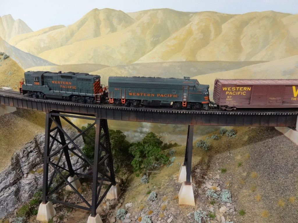
I used Micro Engineering code 83 bridge flex track on this steel trestle. Dry-brushed acrylics weathered the ties to mimic wood, but then again I wasn’t attempting to match wood elsewhere on the bridge.
Once painted and weathered, the transitions in rail shouldn’t look bad.
Coming off the turnout at right is a transition from code 83 to code 55 - that’s a greater difference than what’s you’d be seeing between 100 and 83.
To answer this separately - every manufacturer’s rail is different. If you’re attempting to match Atlas code 100 rail, another brand is likely to have a different cross section, so you’d have to make allowances for that when connecting the two. The simplest way to effect the transition may be to strip rail from another piece of Atlas flex track, as that would guarantee everything matches up.
Thanks Rob as for the painting of the ties, I’ve done some research on that part and seems alot less painful than trying to tack a rail in place on a 22 radius and keep in guage.[:$]