Looking at photos of an HO Brass GEM Models Olympia Ruby Series, READING 4-8-4 Class T-1, there were two vertical appendages hanging below the rear of the cab, and I’ve never seen anything like these before.
Item on the fireman’s side is the stoker engine. Item in the middle is one connection to the booster engine; the long pipe on the engineer’s side is the other, as oldline1 thought.
Ed will have detail pictures on how the stoker engine and booster piping is supposed to be connected; the Brass Trains model was missing the jointed pipes connecting to the trailing truck:
This was from the Reid Dennis collection, so I presume the detail parts ‘went’ with the model when sold. If they had been installed when the pictures were taken, you would likely not be confused.
Looking through the T-1 images at Northeast Railfan I’m guessing the prime possibility is steam supply to a booster engine mounted on the locomotive’s trailing truck,
Water lines from tender and the locomotive’s injectors also appear to be crowded in to that area, so water supply piping is a possibility too.
Looking at following image, play the ‘follow the plumbing’ game and water supply to boiler feedwater heater, some of which appears atop smokebox, is indeed possible,
…following the piping certainly solves some of the piping mysteries: The cold water pump is not too easy to see, but it appears to be between the rear of the trailing truck and the steam pipe connected to the trailing truck. It then ducks behind what I take to be the ashpan doors, then disappears behind the rearmost air reservoir, not to be seen again (it’s supposed to connect to the Worthington S- or Sa-type feedwater heater, atop the smokebox and ahead of the stack. The hot water is then routed to the hot water pump, which is aft of the valve chest and above the valve gear.
The hot water leaves the hot water pump and I’d guess that the pipe just aft of the step in the walkway is connected to a top-feed check valve in that fairing ahead of the sand box.
The steam line for the booster engine on the trailing truck makes its initial appearance just aft of the hot water pump, then disappears behing those two air reservoirs, re-appearing just before it disappears again into the lagging on the side of the firebox. It’s seen again as the large vertical pipe beneath the cab, which connects to the booster engine…at least that’s what it looks like to me.
Some T-1s, the model in question being one, have the stoker engine prominently visible and the hanging cold-water line from the tender (which is missing on the model) below it. Here there isn’t room for the ‘other’ hinged pipe on the outside of the rear of the trailing truck (where it was preferred because all the flexible joints were accessible) and hence they have an ‘inside’ pipe.
Meanwhile on the posted images of engines that do not have the stoker engine in that position, the booster pipe on the fireman’s side comes down at an angle, has a funky canted joint where the J-pipe goes across to the trailing-truck attach point, and I’m pretty sure that heavily-lagged or large-diameter pipe coming out of the firebox lagging is booster-related… probably admission with that heavy a lag; Ed will know definitively.
And yes, I ought to know which side of the T-1 the booster steam supply is on, and no, I find I don’t. The only arrangement drawing I have shows the ‘booster throttle’ (air-actuated)on top of the boiler, fed forward from the steam dome above the dry pipe, angling down the fireman’s side, then exhausting forward on the engineer’s side all the way to the front end, possibly associated with the boiler ring – that was one of the earliest designs; I think the later ones exhausted just behind the stack or to the cistern (the premise being they wouldn’t be operating long enough to heat it to where injectors wouldn’t work right, I guess).
The '47 Cyc is no help and indeed it shows the castings for the E-1 being symmetrical with respect to the external attach points for the pipes…
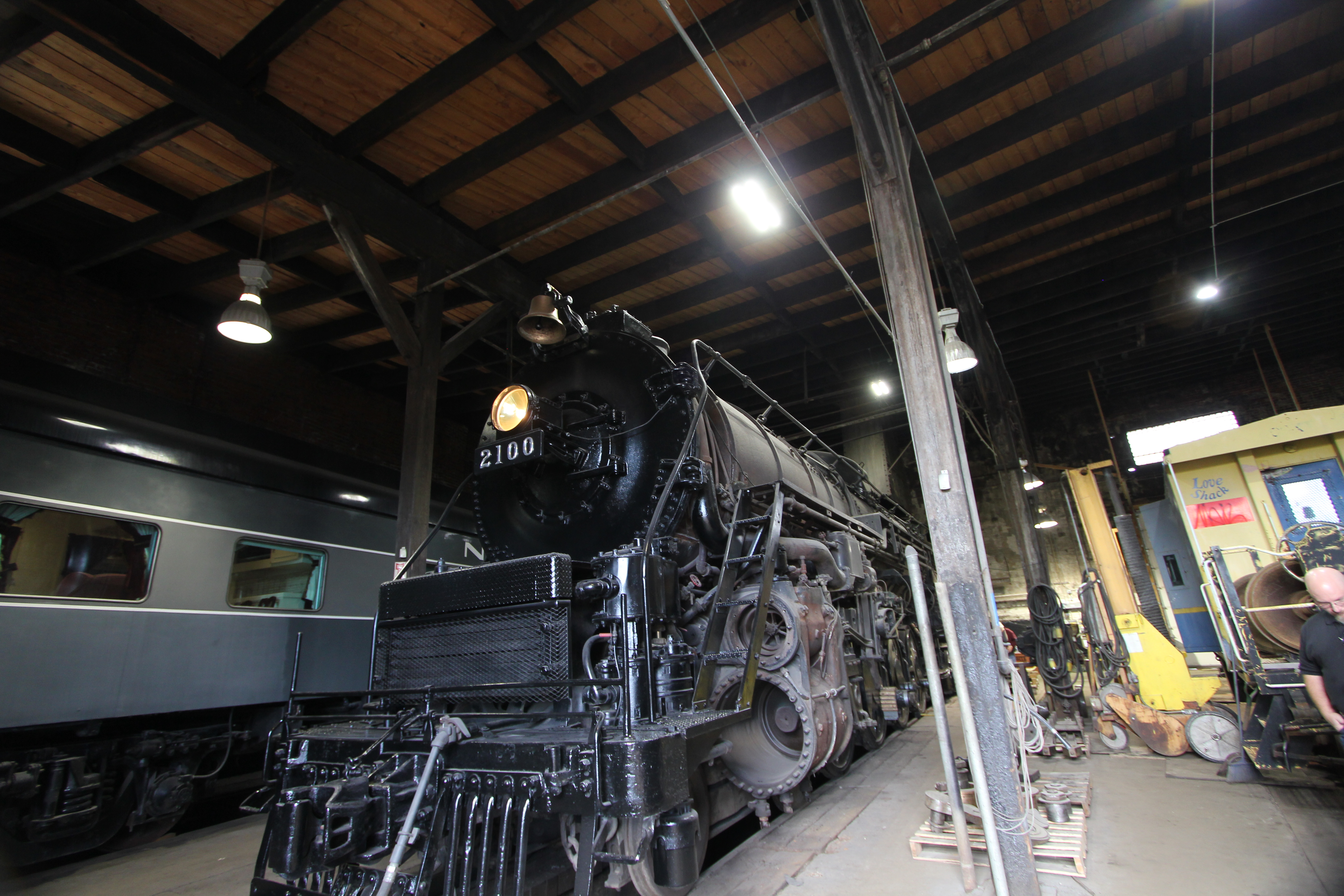
Last summer, I was just looking over the 2100 which is here in Cleveland. Do you think I would have taken any photos of the Franklin E-1 booster? IIRC the piping was removed.
The top image has some typical piping arrangements.
I believe the inlet was from the left, fireman’s side, the exhaust is out the right side of the booster engine but it may easily be switched around so… I can not say for sure on the T-1s.
The outward angle at the bottom of the booster pipe is to clear the water intake piping to the exhaust steam injector. Those flexible, ball and socket pipe joints I’ve always called Barco fittings. Maybe there’s another name for them.
Not suprised there. Even the “big” roads questioned their return on investment and began to remove them in the waning steam years.
I just couldn’t find any reputible information regarding the specifics related to the T-1s. I do recall a story involving, I believe, the 2102 engaging the booster somewhere near Gettysburg in the pre-diesel backup fan trip days.
[edit]
From another account I believe the booster was inoperable, at least on the trip mentioned here:
There were roads, and I believe the Reading was one, that knew how to use boosters and understood their value. In my opinion one place they should have been used, and famously weren’t adopted, was on the production PRR T1s; I know why PRR did not specify them (a very different reason from Kiefer on the Niagaras!) but some of the effects of ‘poor throttle technique’ and the lack of separate throttles for the engines might have been far less marked in practice.
If I recall the story, the booster was taken off during the ‘botched oil conversion’ and was said to be lying around in the open for a while. I think I remember reading that someone came across it, took it to be renovated, and at least planned installing it on another locomotive.
It is amazing that so little apparently exists. I think there was at least one good (meaning technical as well as ‘photo-rich’) on the locomotives, but I don’t own any.
It would be relatively easy to confirm (or disprove) the presence or absence of boosters on 2101 and 2102, and probably on 2124. Certainly they were, and are, as useful for practical excursion running as the unit on NKP 765 is.
From what I’ve gathered there were T-1 parts scattered across the country, begged, borrowed and, perhaps, stolen.
After her “302” stint I know where the elephant ears wound up. We were using them as coal bunker sides at the B&O Clark Avenue yard in the days the GTW 4070 was working there.
I rode the 2102 on several occasions through Ohio and eastern Pennsylvania in the early-mid '70s. Also on one of the two doubleheaded trips with the 4070, Pittsburgh to Altoona. Fired for parts of this trip.


