I am thinking about rebuilding my N-Scale New Haven Layout in the near future. This would be designed to represent a selectively condensed picture of the Providence, Rhode Island area as I remember it in my childhood. I have researched actual track plans and what seems like a million pictures. Some of the areas to be represented are: Providence Union Station, Produce Market, East Side Tunnel, Charles Street Engine Facility, Mineral Spring Street Y with Fox Soda Plant, Northup Yard, Pawtucket, Boston Switch, Olneyville with Blue Coal, Branch Line to Pascoag, Cranston Print Works, Harris Ave Lumber Yard, Electric Plant and Allens Ave area to include the tank farm and scrap yard. There will be two mainlines for continuous operation and enough switching opportunities to keep at least four people busy. An Exchange / Fiddle Yard will be above the work bench and car storage under each yard in a wood six drawer craft cabinet.
On the positive side, you have done a really great job in capturing the flavor and many features of the Providence area for which I commend you. Believe me, I know how hard the research is to acomplish this feat.
Your layout is in actuality just a double track oval, draped around a lot. Trains departing Providence for New Haven will arrive from Boston, and vice versa on the other track. There is no way to effect a realistic replication of the actual operations on the New Haven in the Providence area. Other than backing trains into the station and utilizing the “wye” there is no way to reverse a trains direction.
I am designing a layout based on the New Haven Union Station, much as yours is centered around Providence. In order to replicate the operations there, it is necesary that trains that leave for Boston, arrive back from Boston. Trains that leave for New York return from there. The only way to accomplish that is to use a dogbone type design which has return loops at both ends.
In my case, the return loops will incorporate multitrack staging, which iwill be hidden on a lower level. As was the case with the New Haven and in your plan, the Shore Line will be double track and the West end 4 tracks.
In actuality this is a single track oval, with the centers squeezed together to create a double track main resulting in East bound trains (from Providence in your case) heading to Boston on Track 2 and later, when desired, returning from Boston on Track 1. The track number designations merely change in the center of the return loop at the end.
With staging at each end, you would have the luxury of holding trains, for return when you want them to, not when they are merely running around a loop. Continuous operation is also a possiblity, if you prefer that.
I too think you’ve done a good job catching the flavor of the area. i like the plan, and it’s obvious you’ve done your homework. if im thinking of allens ave (by the tanks) correctly…i’ve always thought of modelling that, with the track running down the middle of the street, switches galore going into a variety of brick structures. again i could be thinking of a different street!! maybe its somthing to loook into to give it some more operation possibilities as well as some great modelling opportunities. I’m semi new to RI so im still learning the street names!
also…if you need some help with benchwork or a operator or someone to help with maintenance…i live a few towns over from ya!!
From your comments, and the others comments, it seems this layout is well thought out. For me, though it is hard to comment on for two reasons. 1) It’s small and the labels are un-readable. perhaps you could post a larger version and give us a link. 2) Like all plans here, you can’t refer to the plan when you comment. I like the fact that you planned for roads and buildings.
In general, The double main line is not so obvious to me. Perhaps that I’m just not seeing the picture because of the track size, but the “mains” seem to disappear into the maze of yards and industrial switching areas so that it’s hard to tell where they are supposed to go. At any rate, this is not a layout where you could conceivably run one train in each direction on the double main and switch a yard or industrial area and not worry.
I wonder why some of the tracks are there. For instance, the yard about 1/3 of the way down on the left does not seem to have any buildings around nor does it seem long enough to do anything.
On the lower right, there is a switchback that only has room for an engine to make the maneuver, or so it seems.
There is a wye and a turntable right next to each other, and the wye is not long enough to turn more than the engine.
On the lower right, the main lines seem to run through an industrial building.
In the upper center, there are several industries coming off a yard to the right. However, there does not seem to be a way for the engine to switch them short of using the split in the upper main line in the upper left of the drawing as a runaround and making several maneuvers to get there while tying up the main.
Again, maybe it is the limited size of the image that makes parts of seem not to make sense. And unlike you, I don’t know the prototype nor it’s “flavor.”
Tip - try right clicking on picture and choose “Open link in new window” in your web browser. Then you can view the picture in one window, comment in another. At least it works for Internet Explorer.
Another trick that works on Microsoft Windows - click ALT+PrtScr to copy screen window, then start e.g. Microsoft Paint (Start | Run mspaint, ENTER) and paste in screen image.
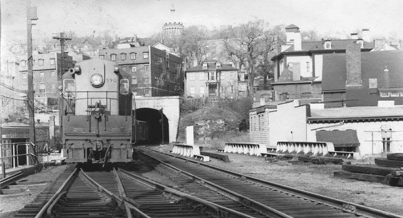
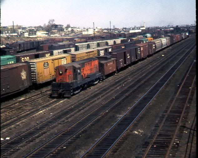
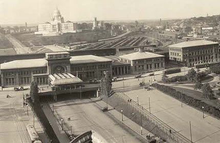
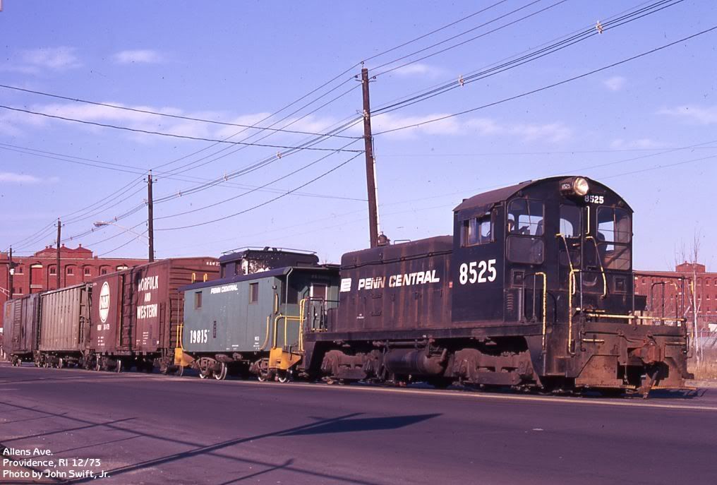
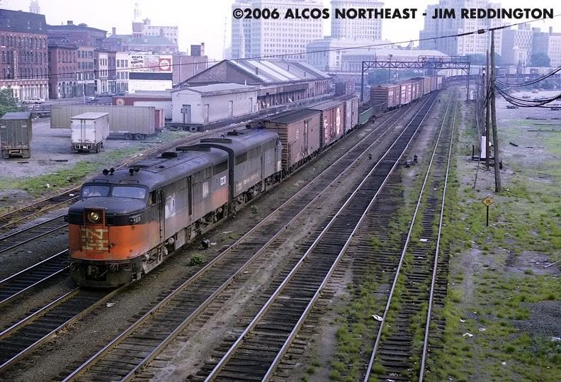
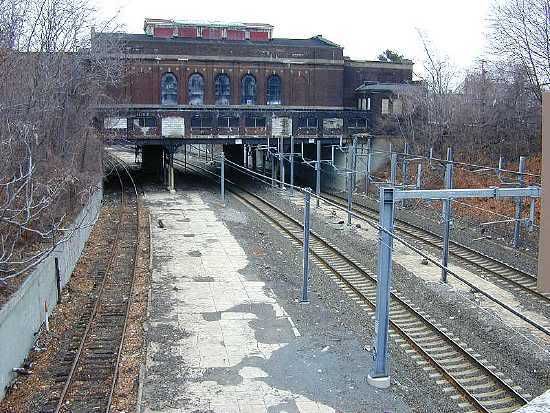
I admit the plan is a little hard to read even when enlarged. Believe it or not, some of the distances are not really reduced too much. The Y was just around the corner from the Charles Street engine facility. And part of the Y was for the Fox Soda company. Granted, a little of this is by memory. I have been a member of the NHRHTA for a long time and have almost all their books. Along with that, I have just about all available pictures of the New Haven Railroad in my computer for reference. The building that looks like the track runs through it, does. It is the Pawtucket Station. the station is/was at street level and the tracks went under. Some of the track routes were just about as they were in the 50’s and 60’s. I had to reduce the mains from 4 track at places to fit in the room and for cost reasons. A couple I took some liberty with as far as the direction they turned and/or distance. Here are a couple of pictures (out of hundreds) I have tracked down on the web.
Sarge, you appear to be very enamored of your plan which is your prerogative. But, why post it if you are not open to suggestions from others as to how it can be improved?
There are several problem areas that have already been pointed out by others. I have to add what I consider is a serious bottle neck on the far left, with what appears to be a double slip switch. Perhaps it is because the drawing, even when enlarged it is not clear there. I recommend, in all cases to keep the main line double track in all places with crossovers, not slip switches.
Main line tracks circumnavigating a small yard on the bottom would foul up yard work. They might better be routed around the south side of the yard, with a lead track on the north side. Any switching there would otherwise foul the main.
You still have the problem that it is basically a double track oval, fitting for a 4 x 8, but not for a larger layout such as the one you are planning.
If you trace the path of a passenger train departing from the Providence station to the East (simulating Boston) and follow it around the loop, you will see that it is arriving tfrom the West (simulating New Haven). Just like on a 4 x 8 “toy train” layout. Believe me, you will soon get bored with just running trains around in circles.
With the amount of research that you have done, you have the opportunity to plan a well functioning model railroad that you will be happy with for years to come. A method that I have successfully used for over 60 years is to mentally operate trains over the planned trackage to find out where the problems are, and correct them on paper, which is far more preferable to having to tear up track later on.
I can see some of your argument for it not being a loop, but more of a point to point. I am tinkering with a plan to have the point where the North to Boston and the South to CT not meet, but go down a helix to a lower level for a long run around. I just have to figure out a method to get a helix into the center of a helix or maybe just real long grades.
As far as the mainline going through the center of a yard, that is the way it was in real life. The New Haven used one side to act as a yard for North bound yard traffic and the other side for South bound yard traffic. Believe it or not, several years after the period I am trying to model, they also added a Wheel Shop smack dab in the middle of the Northup Ave Yard that you have discussed. If I only had the space to model every single track, it would look like a snake pit! I kind of look at it as a challenge to work with what it was like in real life. I wish I could post the actual New Haven documents and maps.
By the way, in Rhode Island, the Department of Transportation also took lessons from the New Haven. We have an unbelievable highway system here. They work by the theory of “How can we design it so it becomes a disaster”. We have more exit and entrance ramps to RT95 in the Providence area per mile, than you can count on both hands. Some cause you to enter from the right and then cross 4 lanes to exit to RT195 on the left in about 1000 feet. Then they add in a ton of curves and constant lane reductions due to the installation of potholes. Yep, they add them so the folks on cell phones, that don’t use directionals, can cause the rest of our insurance rates to sky rocket. If you want a laugh, check it out on Microsoft’s Virtual Earth.
As I commended you on my first post, you have done a really thorough research job. If that is the way the NH yard was laid out, so be it. Sometimes the NH used what they inherited from a prior ownership. Because of the operating problems there, I wouldn’t do it anyway.
Rather than a helix(es), with the amount of room you have you might conisder a pair of nolixes. A nolix is a continous grade that doesn’t run around in circles. That is, from about half way around your loop, extend the track around the outer perimeter, gradually descending to the hidden staging loop below. This would provide a lot more visible running room and take up no layout space that is required for a for a helix.
I start with a schematic track diagram. I draw a horizontal double track. At each end I connect the two tracks with a loop. So it is essentially a single track oval, but with the appearance of a double tracked main in the center, with eastbound trains returning from the east and westbound from the west. Ths is the only practical way to achieve that. Then I add the the crossovers, sidings, yards, station areas, etc. in the order that I want them to appear. That comes from your research.
Now think of this as an elastic track diagram, that can be stretched to increase distance between sidings, stations, or whatever need be. Then you wind it around the available space, laying it down on paper like a length of garden hose.
The result, is a railroad that “works” like a real railroad operates, moving people and commodites from one place to another, not around in circles.
SFC Gadget-I don’t know if this will help any but I have a 1992 issue of MR that features the NH in the steam-diesel transition period.The articles features the route from New Haven to RI.It’s HO but I’m sure you could get some ideas.If you’re interested e-mail me with your address and I’ll copy it and send it to you. Bob
Thanks, Bob. I believe I have that in my library. The catch is to find it. It got a bit out of control a couple of years ago. I have been subscribing to Railroad Model Craftsman, Model Railroader, N-Scale, Garden Railways, The Shoreliner and a few others for over 10 years. the magazines and reference books must be close to a ton by now. I’ll check it out - with as much as I have, you tend to forget what you saw where.
Given the time span since the orignal posting, my constructive comments area little late and probably worthless, But: … First let me say this is the first layout I’ve ever seen that captures the flavor of Providence as it was during the 50’s- 60’s… I’d add one siding for the sleeper pocket street side (the station had 2) , and to eliminate the loop round and round nature I’d cut the loop at Boston Switch and dive both mainlines under to hiden storage and loops… One under the turntable and the other under the wye “west” of the station.
I’d move the 3track coach yard clockwise and lay them parralell to the main station tracks.