Can any of you veterans give me recommendations on which LED’s & resisters to purchase when converting HO locomotives from Bulb to LED? The locomotives are LL proto 2000 (GP30), LL proto 1000 (F3A), and Atlas Trainman (GP38-2). Thanks!
I think most may say warm white or golden white for LED color, I went with 3mm for size. Regular white may be too harsh.
Resistors were 1k ohm 1/4 watt off ebay, I think a buck and change for 10 and free shipping, work very well and no complaints. I don’t think LEDs are as sensative to resistors as bulbs from the research I’ve done.
The below link covers LED’s and light bulbs.
http://www.members.optusnet.com.au/nswmn1/Lights_in_DCC.htm
I mostly used LED’s and a 1k, 1/4 watt resistor.
LED’s are current devices and light bulbs are voltage devices. Little different when you start measuring the operating characteristics.
Rich
For me, these pre-wired and pre-resistored LEDs are quick and easy, plus nearly a direct replacement for the size and shape of the L-L/ Atlas, etc. lamp:
Again, I said quick and easy. There are LOTS of variables out there. On steam locomotives I generally use an SMD carefully cemented into the headlight housing.
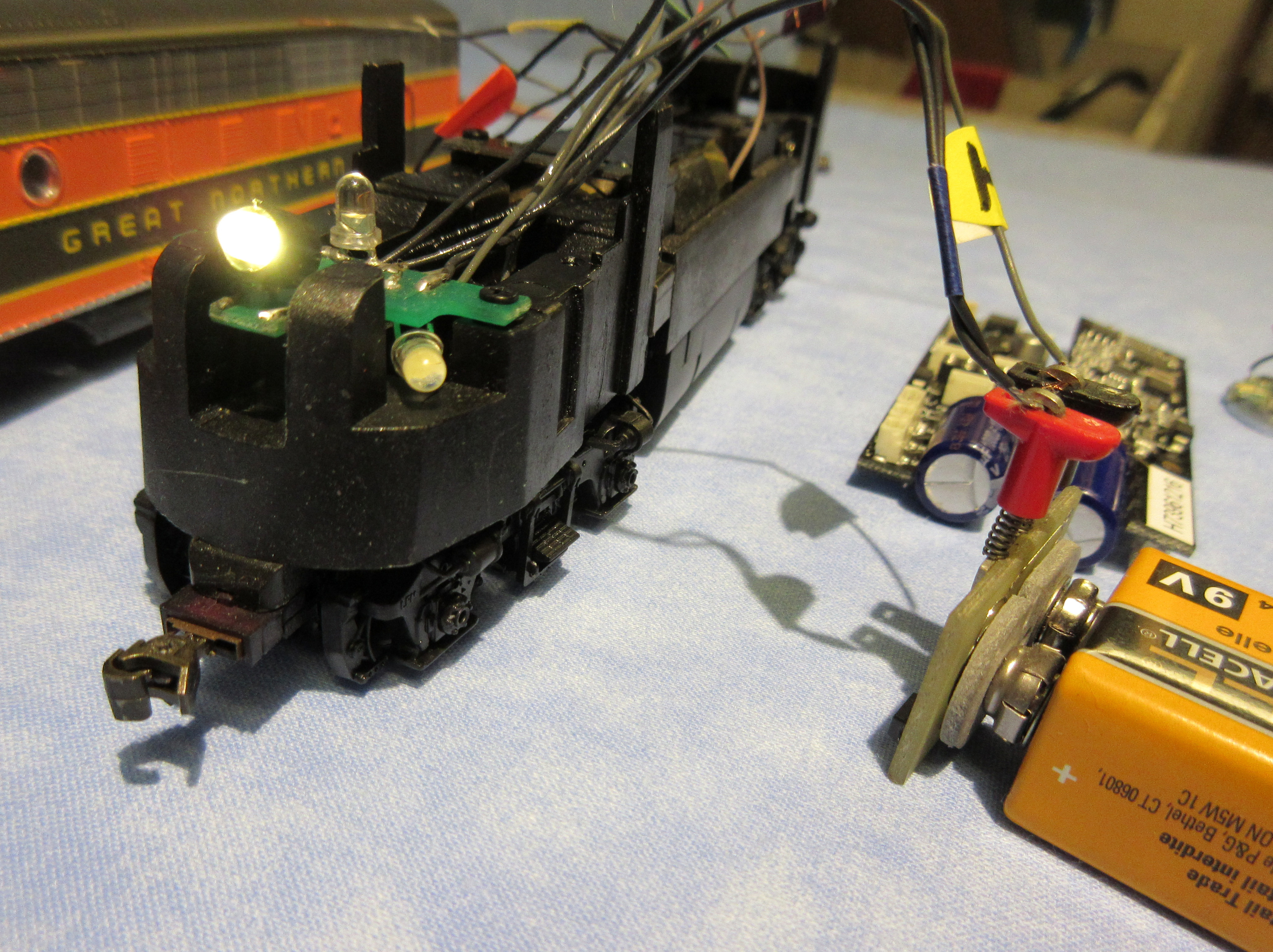
Here’s a pair of the WeHonest LEDs temporarily taped into the original location of the L-L lamps:

and one installed into an E-8:
 LL_E8_DCC2 by Edmund, on Flickr
Look around the WeHonest offerings, there are several choices similar to the one I linked to above, both in size and color.
Sometimes I add other LEDs to illuminate the number boards separately as I like to see these lit all the time.
In HO diesels we usually have the luxury of lots of room inside to play around.
Good Luck, Ed
Thanks for the links, very helpful! Do I need to worry about which lead is the + and - when installing? Is there an accepted uniform color coding that red is always (say +) and black is always (say -)?
Ed, I always appreciate that you take the time to add some helpful photos! Looking at your pictures, I see the LED fit neatly in the manufacturer’s groove and are temporarily held in place with tape. What do you use to hold the LED in place as your final installation step?
Another question a bit further afield. I know you’ve done many DCC installations and have done some milling on the chassis. Depending on which combination of decoder + speaker that I use, there may be a need to mill out the manufacturer’s groove for the rear headlight. How do you in attach the LED headlight in this situation and how do you focus the light out the rear headlamp lens? Thanks!
The more you get into model railroad LED lighting you will want control of the lighting brightness for the LEDs. LEDs are a current devise and use resistors to vary the current. I stock values from single digit to 47,000Ω in both ⅛ & ¼ watt for the purpose.
The Anode is positive and normally the longer lead on a LED. The Cathode side of the LED is normally flat around the bottom rim and the shorter lead or negative.
Mel

My Model Railroad
http://melvineperry.blogspot.com/
Bakersfield, California
Polarity matters, but hookign the LED up backwards, as long as the resistor is in the circuit, won;t hurt anything, it just won’t light up. LEDs don;t have color coded leads, however they do usually have a flat filed in one side of the case, insteadof being perfectly round. The flat side is the cathode, the - side. One lead is usually longer as well, but once you cut them to fit you can’t tell that.
On a DCC decoder, the function wire, white, yellow, purple, green, etc. is always the - side, the blue is the common for all lights or LEDs and is the + side.
It does not matter which side of the LED the resistor is on, it just has to be there. For consistency though you should pick a side and always wire them the same. Electrically it makes no difference.
T1 (3mm) size LEDs fit in the spot in the P2K chassis where the light bulb was, at least on my Geeps.
–Randy
Thanks for the helpful information! ![]()
For clarification, the earlier links were for LEDs with installed resisters that are soldered to electrical wire and covered with shrink tubing, making it impossible to tell which was the cathode and anode. Perhaps Randy gave the clue. A simple test is to connect the LED with installed resistor to a labeled +/- DC source. If the LED lights, I will know which is the cathode and anode. Correct?
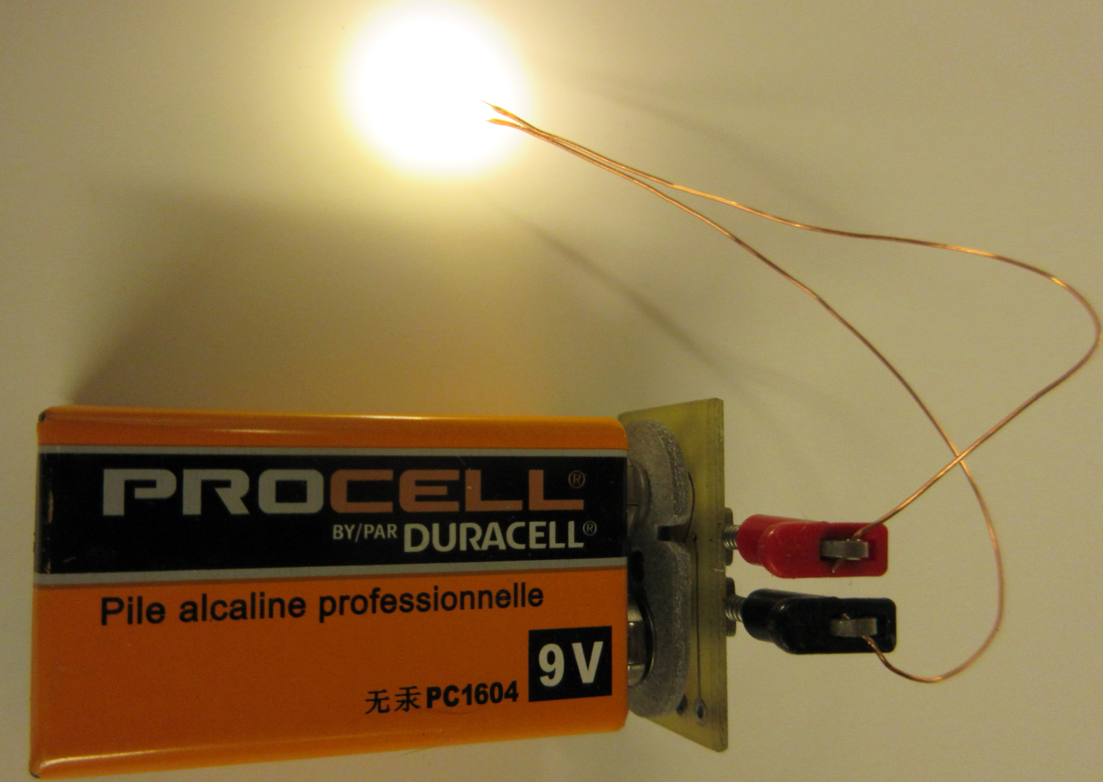
Correct and you can use a 9 volt battery, or a DC power pack.
You may need the installed light pipe for some of your installations. I’ve cut light pipes to a conveniet length, depending on where I am going to mount the led. I polish the end with #600 wet dry sandpaper. You may need to shield the sides of the led with heat shrink to prevent unwanted light leakage.
I use the same clear caulk for track laying, to glue the led in place in the shell or to the back of the light pipe. If for some reason, you need to remove it, it just pulls off.
No one mentioned this, but some decoders, like the loksound direct select, already have a resistor on board, so you don’t need another one.
Thanks Henry! My GP-30’s don’t have light pipes. What do you suggest as a replacement? Also, does it matter if it is light tube is mounted horizontally relative to the headlight lens versus at a slight upward angle? For the speaker install, I may need to remove too much chassis to have a horizontal orientation relative to the lens. Hope that makes sense…
Thanks for the heads up on the loksound decoders.
hmmm
Go to www.Hoseeker.net and look up Life Like GP30 page 3. #3 there are two of them, front and rear have different shapes. They are wedge shaped pieces of plastic with two projections that serve as the headlight lens. It also is the number board as part of that same part.
I’ve never had to create a number board. Glueing something to the back of the hole is going to look weird.
For the paired headlights, I have. Find a clear plastic sprue that held windows for some other building kit. Chuck it in a drill and run it across a file until it’s close. Use sand paper and the drill to turn it to the correct diameter.
I think you want this pipe to be as close to parallel to the tracks as possible.
Thanks Henry! You got me, I had simply removed the shell and set it aside, which of course, is where the lightbars are located… Thanks for the correction and suggestions! ![]()
Basically, there is but manufacturers are not always inclined to stick with it. Life-Like and BLI frequently use all black wire. I often find red on the minus side of the motor. Check the motor rotation/locomotive direction. When the locomotive moves “forward” you have found the + side of the motor.
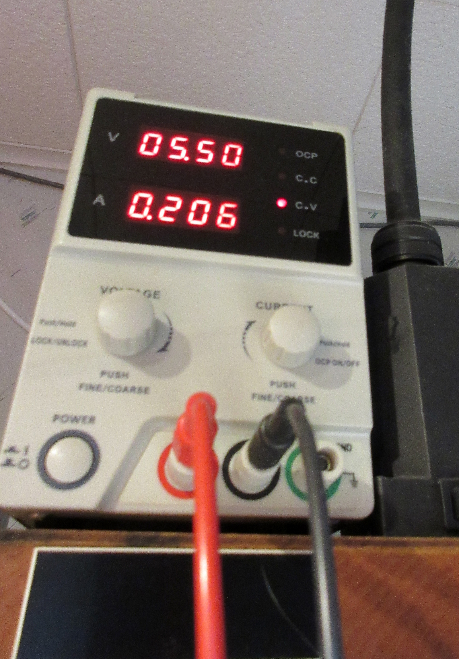
NMRA originally set up DC standards so that IF the right rail saw DC+ that would move the locomotive forward. I use a DC power supply (below) but you can check with a 9V. battery if you don’t have any other way.
Those pre-wired LEDs from WeHonest have black and red leads for — and + respectively. BUT as pointed out, TEST them first. This is the handiest LED tester I’ve ever seen (can’t find them anymore) I think I got mine from Lloy’s Toys or Tony’s. You could make your own.
 IMG_4764_fix by Edmund, on Flickr
 IMG_7094_fix by Edmund, on Flickr
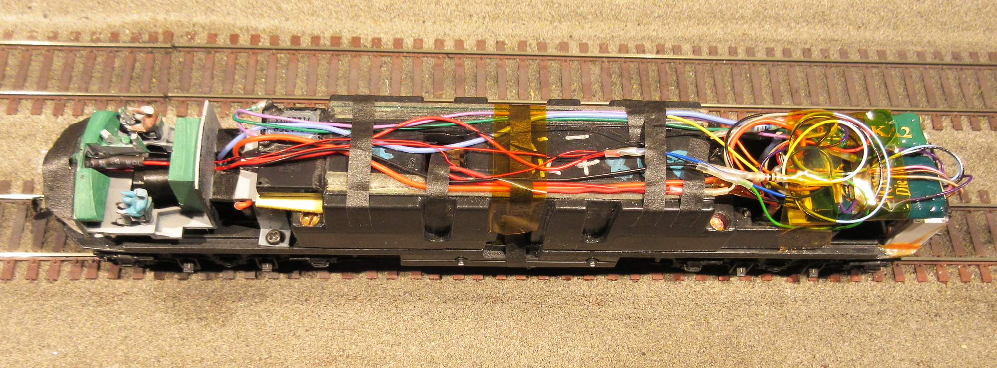
I’m using it here to “ring-out” the wiring (all black) to the PC board on this BLI F7. with two number board, a headlight and a Mars light AND a cab light! By sorting these wires out I know what has to go where. This is also a good case of “if it ain’t broke”
Thanks for your time and effort Ed! Always very helpful and instructive!
A little off-topic maybe, - how would i wire an LED in an F7A so the headlight is always on (no rear lights) - I am guessing that using the blue (with a resistor) and white decoder wires keeps it on going forward; can I
also connect the yellow to the white so it is lit when the engine reverses? or is this (electrically) bad for the decoder? or, run the yellow through a diode to protect the decoder? and maybe add a small resistor to the white connection so it’s dimmer when going in reverse? [I admit to being mechanicaaly-inclinde, but electically-declined in nature…]
Hi,
Most recent decoders will allow you to choose F0 options so that the headlight will be on in both directions. I did one like that where the headlight was on bright while moving and it dimmed when stopped. Another case I had a switcher that I set up to have both headlights dim in both directions but you could press F7 and the headlight would be bright in the direction of movement and the other one stayed dim.
Look up lighting options for your particular decoder.
In other cases I “hot-wired” LEDs right from the track pickups. Bypassed the decoder alltogether. I sometimes do LEDs for number board lights this way.
Just an LED and a 1.5 to 2.5 K Ω resistor in parallel with the rail pickups.
Good Luck, Ed
Thanks, Ed; I like the option to hotwire the LED, and I am already hard wiring the power from the trucks so its an easy approach as I rebuild this BlueBox loco. I have a 2–wire microconnector so I can separate the shell if Ineed to in the future
Hot wiring of course prevents you from ever turning off the headlight. My prototype, for example, didn;t actually use headlights in the daytime in the era I model (I have a rulebook). Most decoders allow you to set teh F0F output (white wire) to be non-directional, so it can be on or off in both forward and reverse. However, in the event that the decoder is not configurable for this, it is perfectly safe th hook both the white and yellow wires to the - side of the LED and the blue wire to the + side (with a resistor in there of course). The way the decoder function ‘outputs’ work, you can always create an “or” condition by hooking 2 or more function wires to the same light. When you do so, the light will be on if one of the functions is on, or the other is on, or both of them are. I don’t think anyone offers the complete freeform mapping of functions to buttons that ESU does, but you can sort of get around it by connecting multiple functions to the same light.
–Randy
So I have yet to map a function. I will have to dig out the Kalmbach book on this topic and see how difficult it is. But from what you said, i could connect both with a resistor in the Blue wiring, and a smaller resistor in the yelow wire: when the loco backs up, the headlight should dim; am I reading that correctly? alternativley, I will dig inot hte decoder manual for this DH 123 and see if it features Rule 17 lighting, which ( IIRC) will automatically dim the forward head light wehn the loco backs up?