You sound like you have a basic plan. You cna go wiht that if it makes sense to you. There is no right or wrong…just different ideas.
Most of us have a drawn map of the layout control panel or on the switching panel or fascia board to place the switches that control the switches {also called track turnouts} on it where the switches{turnouts} are located.
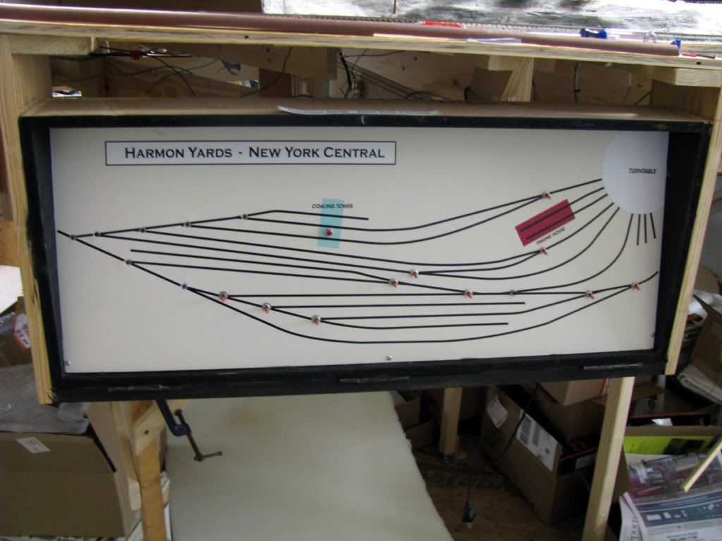
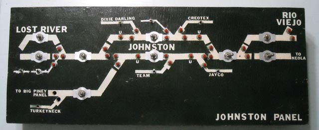
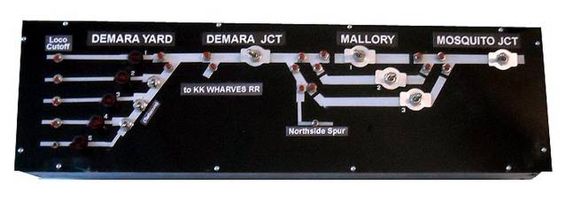
This can be done using pinstriping tape over black painted plexiglass with holes drilled for the {toggle} switches to control the turnouts in the shape of the layout. This is the control panel.
Others paint lines on the fascia or swtich board.
If you are using the Atlas ready-made included momentary slide switches, they can be mounted on the spot on your layout map where the switch is, OR they can be lined up in numerical order, say left to right to control clockwise on the loop they are located in.
Eample: you have 4 turnouts on the outter loop One at “noon” one at “3;00” and one at “6:00” and one at “9:00”…align the Atlas momnetary switches up left to right for each number 1 through 4 signifying on the loop as the switches gofrom top{noon would be switch #1} to right {3:00 would be swtich #2}to bottom of loop {closest to you would be atlas switch #3} and then left to the top again. This way you have it naild to locationa dn which Atlas switch controls which turnout.
Really fancy modellers use a light system to signify which way it is thrown on its control pannel. If the LED is green by the switch it means aligned to straight away, red to tangent, for example. Others just know by which direction the toggle switch’s lever is pointed, others know by which way the Atlas switch slide is slid to.
I have a small layout and the four front turnouts are right in from of me are manually controlled. I can easily tell by looking at the track which is which way, and I throw them manually,. I can also tell which way they are aligned by the position of the maunal switch lever throw bar.
My DCC HO layout has 96 remote switches, so using the DCC 4 digit/switch was not feasible. I divided my layout into 4 power districts, such that each of the four operators control 24 remote switches, that are numbered on a diagram of their district. By using a common ground for all of the remotes, and having two wires from the switch to the 24 double pin terminal,one uses a grounded probe to momentarily touch the proper numbered pin terminal for straight or curved. Click on the photo to enlarge it. Then click on “Previous”, or “Next” to see other views of my layout. Bob Hahn
If DCC, then you can install addresssable accessory controls on the switch machines and control them via DCC. I use NCE and it indicates the position of the switch, in addition to letting you control it via DCC.
Another way I use DCC to control switches is in my staging yard. I programmed macros for each of the 7 staging tracks. Each macro throws all the switches at both ends of the yard throat of the selected staging track to line them up. All I need to do is enter the correct macro number for each staging track and then everything aligns to take a train in and out of staging.
You can also use macros to set up a route through complicated trackage.
Make a diagram of your layout and put toggles or push buttons (depends on type of switch machines you have) and then you will know exactly which turnout you are controlling. Mine is a little more ‘sophistacated’ but any drawing on a panel will work. I had mine printed at a local print shop from my artwork done in Corel Draw.
I can tell you what I do - I make a diagram of the plan, print it and then laminate it between plexiglass. Then I install push buttons for each switch and lights which indicate the direction it is thrown. The system works for me so the answer to your question might be to research some options and them develop a system that works for you.
I bought a 4x8 foot sheet of white plastic-coated hardboard. It’s used for lining bathtub shower enclosures. I paid about $9 for the whole thing at Home Depot.
I cut this to a convenient size, drew a track plan, drilled holes for the toggles and then went over the lines with automotive pin-striping tape. It’s cheap and easy, and I can add to it easily as needed.
One thing I would recommend is to NOT use those Atlas pushbuttons. They have a poor record for reliability, in my experience and that of others. They also are awkward to use on schematic track plan control panels like the pictures above. If you’re using twin-coil switch machines, get or build a capacitive discharge circuit to make them work better and protect them from burnout if a toggle sticks at any point.
Nice panels, guys. Done my share of that and they just work once done right. I gotta tell you though, all the work and wire it takes to build them is one reason why I converted to DCC addressable accessory controllers near the end of my layout building phase. It saves a ton of time and wiring. The only thing I didn’t do was set up a separate booster just to drive the accessory circuits so that you can still throw the turnout that someone just stumbled into and shorted.
One thing that I also do is simply put the turnout control switches on the fascia directly opposite of the turnout it controls. That’s what I did for most of my layout, using panels only where there was a yard or other concentrated trackage that made using the panel a better solution.
Bottom line is that there’s no single solution to doing this. Analyze how many turnouts you have, how close they are in relation to each other, how complicated the track is, etc, then apply the solution that works best in each case.
The one thing I have seen done badly with panels are layouts where ONLY panels were used. Problem is that sometimes they control turnouts too far away to see, which is sort of counterproductive.
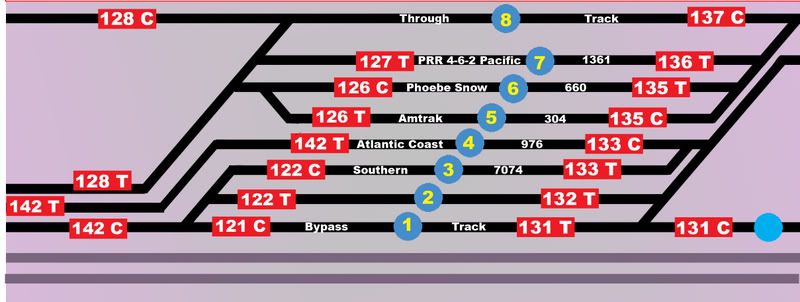
I use Digitrax DS64s to control the switches. I have panels around the layout, but they have no wiring, they are just graphics with switch or route numbers. (The number in a blue circle is a route that throws all the appropriate switches with one command. The numbers in a red rectangle is an individual switch)
There are a lot of “depends on” stuff here. What sort of switch machine are you using? tortoise machines can have power sent to them all the time and only need a DPST control switch. A twin coil machine needs a center off DPST as they cannot be allowed to see power all the time, can’t get rid of the heat.
Push buttons aren’t the best for tortoise as an operator would need to hold the button until the transfer is made and if the turnout is out of sight that is not practical.
I use bat handle DPST center off switches on my twin coil machines. I have not tortoise or stall motor machines.
All bat handles are operated vertically, that is up for the track that leads away from the operator and down for the track that approaches the operator from a location standing in front of the area of the railroad in question. This is moving the bat handles in the direction that would be shown on any of the control panels shown above. My operators have gotten on to this pattern and seldom look at the control panel; they only watch the train operating and don’t need to divide their attention.
Here’s one method that has served me well the few times I used remote switches on my switching layouts.
Like the prototype I number my switches starting with 1 like this, 1,2,3 etc and crossovers would be (say) 7A,7B…I then put the numbers on the switch control and tape a index card next to my power pack that tells me the location of the switch like this,#1 Carter Distribution,#2 North American Plastics,#3 Mid State Tire distribution 4A/4B crossover,#5 Transload track. .
Another way was the #1 switch was the first switch on the left and the rest followed in numerical order and the first crossover was (say) 5,6 and the next switch in line would be-yup #7.
This saved me from having to pay somebody to build and install a control panel since I never could figure the wiring.
However,90% of my layouts used manual switches with Caboose Industries ground throws.
First you need a panel with your track schematic on it. Then you need some kind of lamp (or LED) indicators to indicate which routes have been set up. Having dwarf signals in equivalent places on the layout is also handy. If your point-throwing controls aren’t integrated into the panel, which set of points is powered by which controller should be clearly labeled.
My own powered turnouts can be controlled from two (or three) different locations. On the main panel, points which would normally be controlled by a CTC operator have rotary switches installed in appropriate locations - the switch position indicates which way the points are aligned. The zone panels also have rotary switches for the same point sets, but those have another position which transfers control to the Main (CTC) panel. In addition, remote-powered switches removed from the zone panel can be operated by inserting a switch key into a receptacle on the fascia - sort of like a pushbutton without the button. This is all standard with the MZL system of control, but can be used with DCC just as easily.
Chuck (Modeling Central Japan in September, 1964 - with powered points in hidden places)