I’m looking for some input from more seasoned hands on my layout design. I’ve narrowed it down to two options, but after reading some posts here and realizing how easy it is for Mr. Murphy to enter the equation, I figured I’d seek some experienced advice before I ended up with an expensive mess. I do plan to continue refining one or the other when my copy of Track Planning for Realistic Operation arrives.
First, the givens and druthers:
Givens:
Industrial switching and engine yard in layout
Proto-lance based on the Arcade and Attica for setting/industries (industries tbd)
6-driver motive power (USRA 0-6-0, Ten Wheelers, Moguls)
4-car trains with caboose
1-2 locos per session - 1 switcher fetching trains from staging and 1 main running/servicing industries.
Probably code 83 track
DCC (eventually, may go DC to start)
HO scale (I know I can pack more in with N, but I like the size and detail of HO)
Mid-1930’s era
Switches will be powered and thrown from master panel
Total working space is 18’ x 4’ (half of a long, narrow basement with doors at either end)
Single deck, no helices/severe grades
Druthers:
Continuous run with 20-22" radius curves
8-driver motive power (USRA 0-8-0, Consolidations, Mikados)
6-8 car trains
Potential for expansion/movement within 10 years.
Run Hogwarts and Polar Express trains for kids (not immediate concern, but within 2 years).
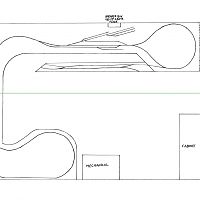
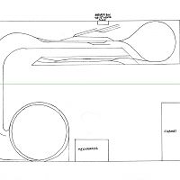
And these are the plans I’m looking at, drawn in 1/2" to 1’ scale (both inspired by Byron Henderson’s work, which I admittedly fail to do justice):
This one incorporates most of my G&D, but the reach may be
18’ is a decently lon side. Is the 4’ width absolute? If that’s half of the basement, you could go 5’ on the layout and still have a 3’ path, or maybe 4 1/2’, with a 3 1/2 foot aisle, which opens you up to 24" radius curves - not only nicer for the trains to run but larger radius = greater elevation change for the same grade.
Taking yet another idea from John Armstrong - how about a loop at one end, main meanders down the length of the layout, some of it level, some of it slightly upgrade. Curve back at the opposte end - but not on to itself, on a grade. Then back the length of the layout again with mixed level and grade sections, to another loop stacked above the first one on the bottom level. Then you get continuous running, and that run is 4x the length of the layout. There are several published plans like that around. A bit more complex to build but you get a much longer run and better scenic opportunites (unless you hate mountains). The lower loop would be mostly hidden, the upper loop mostly visible - good place for a soaring curved trestle.
Unfortunately, the 4’ width is absolute. The house was a side-by-side duplex that was opened up by my grandparents. There are doors right at that 4’ mark that lead to the laundry room on one side and my wood shop on the other.
But I’m intrigued by the idea of the loop with the grades. Do you have an example link perchance? It sounds like some of the long, easy spiral multi deck layouts I’ve read about. I toyed with an idea like that originally. If I left an 18" aisle between, I could still have 15" deep shelves for the layout, and it’s going to be a single-oper
Perhaps, but it wouldn’t work well. It would be a court of last resort. And I could only do it on one end as there is a built-in cabinet in the way on the other end, on the other side of the doorway.
I like the looping plan. I’d have the interchange yard/car swap-out tracks in the front, then a medium grade around the loop to the industries along the wall. Cross a creek along the way. The other half loop can be hidden in a tunnel so the railroad would operate like a C but with a continous run connection. The middle of the layout should not be deeper than about 30 inches for comfortable reaching back to the switching area. That would be a challenge.
I would want the industrial area to be as shallow as possible, so I would have most of the industries be kitbashed building flats no more than 4 to 5 inches deep, if that, along the wall.
As designed now, I don’t know if everything will fit since the turnout frogs look pretty aggressive.
I’d use 0-8-0s and 0-6-0s. Proto makes good models of those locos for pulling a short train (their pulling power isn’t great)
The turnouts in the sketches aren’t really scaled. I’d be using #6’s. The sketches are just for a general idea. I’ll lay everything out more precisely once I figure out how I want it all to go.
I hadn’t thought of pushing the industries to the wall and using flats, though. That would allow me to push everything in more and reduce the reach…
While not a “permanent” piece of the layout in the sense that it is always set up, there may be opportunities for a drop down section or perhaps the ability to have a module that rolls over and connects.
Just a couple notes as the writing is a bit hard to read in places: The breaker box is on the top wall, and is about 12" wide and it goes from the ceiling, down about 2 feet (so from 4-6 feet above the floor). The doorways are not even, the laundry room door being about 1" narrower. The back wall (at the bottom) leads into a crawlspace, and can’t be blocked. That, combined with code-mandated clearances around the furnace and hot water tank (Mechanical), mean that the bottom-right section between the cabinet and the Mechanical area is totally unusable.
Just to clarify, the crawlspace access is between the mechanical (furnace) and the built in cabinetry?
Gears are turning inside of my head, and I’m starting to smell smoke, but if a lift gate or similar was employed, it almost seems like you could include a small curved “yard” in that bottom left corner, simulating the interchange with the BPRR. A wye could nearly be shoe-horned into the upper left corner, with the enginehouse and passenger station (the A&A “office” by the looks of things on Google) upon the upper wall around the 4 foot mark, and continuing along from there.
The A&A is an interesting prototype. I’m stuck home with a sick munchkin and have been playing with your space in XTrackCAD all morning, picking random industries and fitting things in, playing with different ideas. I think with careful seperation between “front” and “back” of the scenes, you have a great space and a really interesting prototype to freelance.
As a side note, my full time job has me producing some bits and pieces for one of the previous customers along the line that manufactures wood products.
Sorry to hear about the munchkin. Hope he or she gets better soon.
Actually, the crawlspace is all along that back wall, but given the clearances needed for the mechanical area, and that that point is the easiest to access (there’s a step there that matches the height of a 2’ step ladder), I figured I should just rule that out for construction. I could use the workshop side of the room (lower left), but I’d just have to allow an inch or so from the wall so the crawlspace can ventilate.
I’m getting what you’re saying about the curved yard for the interchange. I had toyed with putting in the wye that was just beyond the engine shed and station (and yes, that’s also the office) but ruled it out for space reasons. I’m starting to think that the roll-away sections you mentioned earlier might have merit, too, and allow more railroad with less “dedicated” space, which would surely please the boss.
FWIW - I picked that prototype for a number of reasons. Nostalgia (I rode their excursion with the Ten Wheeler every summer when I was a kid), hometown pride, and also because the scenery in that area is just gorgeous. Also, there was an interchange with the Erie just north of Attica at one time, until Tonawanda Creek flooded and they abandoned that section, so now it only runs as far as the Buffalo Molasses plant in North Java. But I was always curious what “could have been” given more economic success and a bit more luck with Mother Nature.
It’s an interesting and modelgenic prototype. The September 1978 Model Railroader article by Harold Russell is a very helpful reference, although I don’t especially care for the track plan that was included.
I worked on a project for client in slightly more space for the Arcade & Attica assuming that the line north to Attica stayed in service for a while longer. This allowed interchanges at Arcade Junction (PRR) and Attica (Erie). This track plan was only about 50% complete before the client moved to a new space and changed modeling focus.
As Randy suggested, that design used stacked loops for the end points of Arcade Jct. and Attica. These could have been partially hidden by scenery and/or scenicked as the connecting railroad. Contrary to real life, we placed Attica above (it’s actually at a lower elevation), which allowed us to use a flat for the infamous Attica Prison (switched by the A&A in real life) and made some other things easier.
The rest of that layout was not as deep as you are proposing. Even with long arms and low layouts it can be really difficult to reach in more than 30” without damaging scenery and structures near the front edge. The need for access to the wall also suggests narrower benchwork in that area. Benchwork edges can curve and benchwork depth can modulate – this is a great tool that many newcomers to design fail to employ.
For continuous running in the stacked-loop schematic, one would need to use automated devices at each loop to sense and flip the return loop turnouts, but this is straightforward with DCC and units are available off-the-shelf. (Speaking of turnout control, I’d strongly suggest not placing all of them together. Much better for operations to place them near where you will be working in each town.)
As Granite Railroader wisely points out, considering the overall space may yield a better result. Are there doors swinging into the layout space, or do they swing away? This
I’ve seen and downloaded the article you’re talking about, and we’re of the same mind about the layout they propose. There’s another one floating around for a garage-sized version, but it’s also more geared for running rather than operation.
I see now that whatever I do, I’m going to have to narrow things some. I had a feeling I would, and your comments about that were the last nail in that coffin. One thing I want to ask about the curved benchwork though - I’ve always read that you should not parallel the edges of your benchwork (if you can avoid it), as it detracts from the appearance… is that mostly for straight lines or would it apply to curves as well? I know beauty is in the eye of the beholder, but that guideline has always beena bit hazy to me.
The doors do swing out from the layout room, into the laundry room and workshop, respectively.
And thank you for the input on the switches and wyes. I’ll bear that in mind when I begin firming up my plan.
Per your comment earlier about Googling the A&A, if you look at the Curriers station on Google Maps, you can see their 2-8-0 finishing a runaround move on the passenger excursion.
This is mostly personal preference, but I would primarily apply the “don’t parallel the benchwork edge” rule-of-thumb to straight sections.
In actual practice, I mix things up a bit. I will sometimes make the track parallel to the benchwork edge to accentuate an area on the (real or imagined) prototype where the tracks were tangent (straight) – such as in a yard area to contrast it with curving track elsewhere.
And many times, you just don’t have a lot of choice. In coiling the desired amount of mainline into the space, allowing the benchwork to parallel the track is the only way to maintain aisle width and access in the given area.
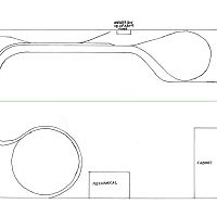
So, not to restore a zombie thread, but to acknowlege and thank everyone for their input, here is the finalized design I’ve come up with for my Tiorunda and Thrace branch line. The input I received was invaluable.
I ended up going freelance with influence from the A&A, because I just felt I couldn’t do it justice, and the constraints of prototype railroading proved a bit too confining. I may expand to include it later, as my fictional branch line does connect with it in the north.
So, I’ve decided to build in three phases. The first phase will include the engine yard/station area, town industries, and return loops at either end.
Some slight modification will be needed with a turnout at the left side of the lower return loop, and maybe with my removable staging yard. Also, the northern spur in the top-left corner isn’t quite plotted right due to a pen slip. But it’s good enough to work from.
The second phase will see the lower return loop removed, and replaced with a helix to the upper deck:
The upper deck will feature a siding with two industries and a return loop representing where the TNT meets the ARA at Arcade Junction.
So there it is. And yes, I know there are still a couple long reaches, but I have planned access panels to deal with that. I don’
It’s actually not blocked, per se. The layout deck is a good 8" beneath the box, and the box can be reached from the front of the layout. This is sufficient for code. Just in case, I’ve designed a lift-out panel into my benchwork. There’s another lift-out at the door to the workshop.
I got design input from a local electrical contractor who knows the codes, and he says that it should be fine. The code here is that the box simply has to be accessible. Since it can be reached, opened, and the breakers thrown from the front of the layout, it’s fine (tested with a piece of plywood that length at the height of the layout). The lift-out is extra insurance.
Between now and the time I add the second level, I may need to move the box anyway for other reasons, so I’m going to let that develop as it will and work around it.