[#dots]
My original 4’x8’ layout had two reverse loops, one within the main oval, and one which could be switched to track outside the oval, which was then elevated and crossed the oval on a truss bridge and a wooden trestle, then returned to the other side of the oval, at ground-level.
Each reversing loop was electrically-isolated (both rails) from the rest of the layout, and there was a double throw switch which controlled direction within both of those loops, as only one would be in use at any time.
Before the train entered either loop, the direction switch for the loop needed to be aligned for the proper direction. While the loco was within the isolated loop, another switch, which controlled direction for the rest of the layout, would be re-positioned to allow the train to continue without need of stopping.
Here’s a rough sketch done from memory (click on photo to enlarge)…
.jpg)
The layout, built by my father, was Atlas brass flextrack on fibre ties, with all but one turnout also Atlas, buit from kits. The non-Atlas turnout was a scratchbuilt #8, again done by my father.
All turnouts were remotely controlled by use of choke wires, which rotated an under-table mechanism to move the points (I wish that I had taken photos of that mechanism, as it was very easy to use, and included rotating targets on the switchstands.
All locos and rolling stock had Kadee K-type couplers, and there were multiple uncoupling ramps, also remotely activated from the control panel.
Wayne
[#dots]
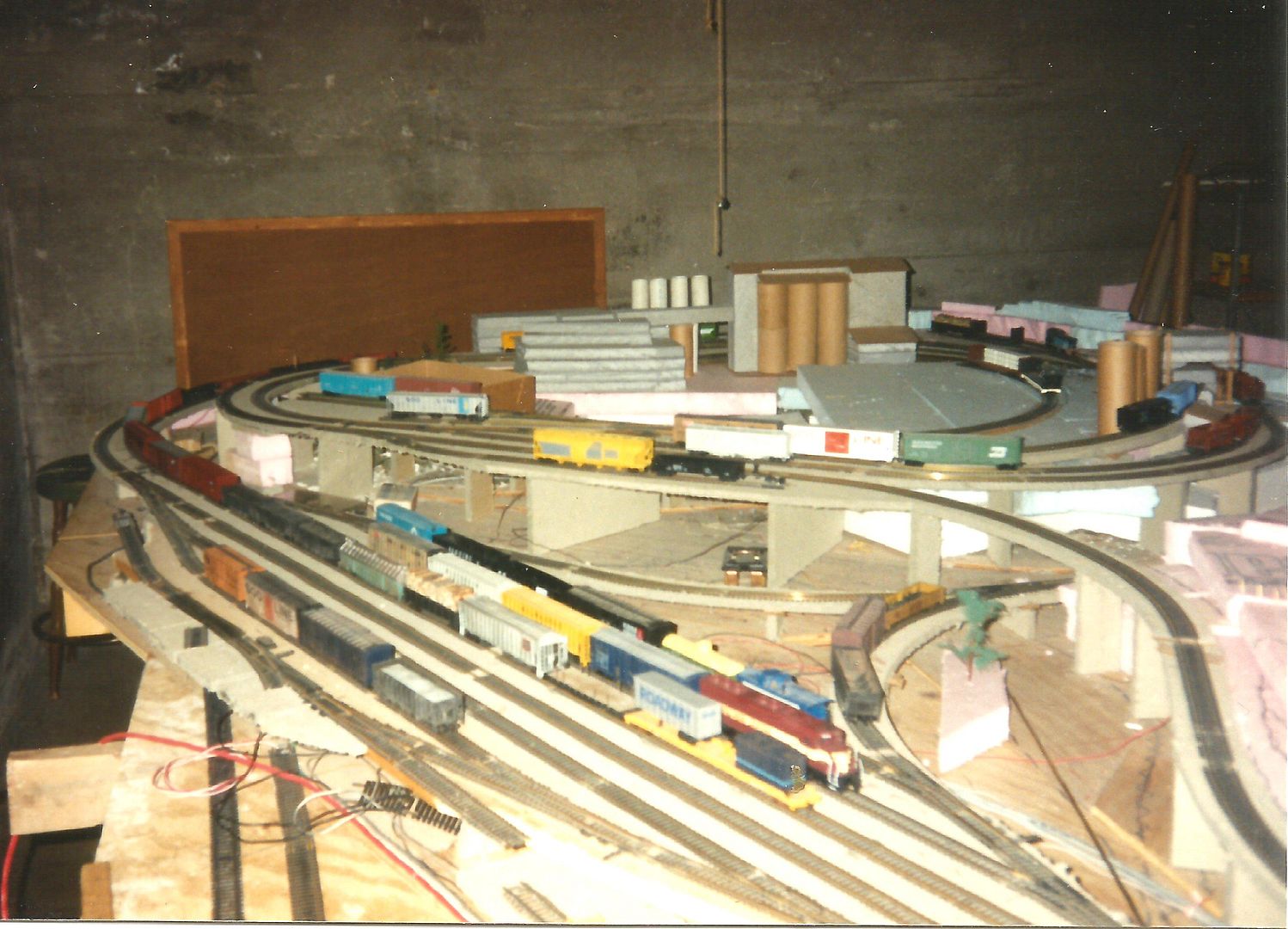
In the late 80’s, I built this:
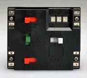
The “Y” needed a reversing switch, so I used the Atlas #220:
Mike.
I started out in HO in 1951 as a 14yr old. I pretty much self taught myself how to wire my layout. I used blocks back then and still do. All blocks have a DPDT center off toggle switch with a home run from the track to the switch.
When I started my current layout in 1989 I went with block control, I guess after using block control for 38 years I was comfortable with throwing switches.
When I cutover to dual mode DC or DCC I made an attempt at following the DCC Guru way but it dinged all my signaling so I rewired it back to original DC block control. The DCC operation works as well as the DC block operation.
I purchased an MRC Prodigy Advance² DCC System, I had used MRC power DC packs for 50 years without a single problem.
The DCC system has worked perfect on my block wiring since day one.
All that to get around to saying if it was my layout I would go with the DPDT toggles, simplest way, KISS!
Mel
Modeling the early to mid 1950s SP in HO scale since 1951

My Model Railroad
http://melvineperry.blogspot.com/
Bakersfield, California
I’m beginning to realize that aging is not for wimps.
[#dots]
[#dots]
Not the Mike you mean but the 220 is quite clever. Atlas has a schematic in the wiring book if you’re interested.
There are three reversing switches. Two red and one grey. The red ones are basically the twin switch (one red switch and the grey switch form a twin switch) and replace the powerpack’s reversing switches. The powerpack reversing switches are left in forwards (or reverse if you want to get confused) and not used at all. The grey button only reverses polarity in the reversing loop/wye/turntable circuit.
The 220 is designed for common rail.
The tricky part about the 220 is the Atlas instructions are a tad vague. If you look at the figures in the wiring book or the diagram on the back of the package you’ll wire it incorrectly. If you examine the schematic you’ll see right away that the instruction diagram is incorrect.
The common rail polarity feeds the top and bottom left side terminals and connects to the track through the left terminal of the three top side terminals that power the reversing loop. That common terminal feeds the common rail for the layout. The figures and the packaging seem to indicate that the powerpacks are wired to the four left side terminals + - + - but actually it is + - - +.
The inner two terminals on the left side feed the block power polarity. Those flow through to the outermost terminals on the exit side (right side) of the 220 which power the block sections in a common rail system. Because they line up it looks like those should flow through from the common rail inputs but they do not.
The green button selects the two cabs and connects the selected cab to the reversing loop. It’s like a block selector switch.
Kevin,
Great article. I will keep it simple but ultimately move to some form of automation.
Dave K.
The Atlas twin just replaces the powerpack reversing switch providing separate polarity control to each circuit. Without the separate polarity control for both circuits you have to stop the train. Not sure why anyone would want to wire it that way.
Since you never use the powerpack reversing switch the Twin Switch wiring is no more confusing than Option 1. A Twin Switch is just two DPDT in one package. Handy, if they aren’t defective!!
To add to Option 2 the turnout controlled polarity switching capability described as an option to Option 1 you need only provide main line powered track sections between the turnout and the reversing loop gaps long enough to accommodate your locomotive consist. Then you reverse polarity of the main as the train fully enters the reversing loop and throw the turnout to the exit lining only when the locomotive consist leaves the reversing loop but before reaching the turnout. This shortens the reversing loop.
We have found that with the MRC 780 at least you can cheat on train length and the very brief shorting caused by metal wheels on trailing cars crossing gaps does not throw the breaker. Haven’t checked the rails or rolling stock wheels for pitting.
This will not work for DCC because decoders can react to very brief shorts but in that case we will wire those short main line sections to be separately switchable to align with booster phase correct and use switchable Ito reverse units for our three reversing loops. These have to be switchable because DC power and autoreversers are incompatible.
Here’s an instruction pdf from Atlas.
http://download.atlasrr.com/pdf/Item220Instructions.pdf
To keep the flow of the train smooth, I remember I had to be watching, and ready at the switch. Nothing was automatic like todays DCC auto reverse controlers are.
Mike.
Yes, that’s the diagram that is incorrect.
You’ll note it appears as though the two cabs are wired to the four left side 220 terminals in the same relative order: + - + - . If you do that the 220 will be short circuited internally. You can ask me how I know this and how long it took for us to figure it out. Thanks Atlas.
If you look at the schematic wiring instead of the figure you will see immediately that the four left side terminals are + - - +. The schematic unfortunately orients the red main reversing switches as if they are up/down when they are actually left/right.
The easiest way to see this is to trace the C or Common rail track terminal (left most of the three terminals across the top edge) back to each Cab’s reversing switch on the 220. You must not try to use the actual powerpack reversing switch, nor indeed any reversing switch in a gang of more than one 220 except for the one closest to the track power connections.
The clever part about the 220 is the way it powers the reversing loop separately from the main but uses just the one Common rail terminal to do so.
If you gang more than one 220 you must not use the reversing switches nor the C terminal in any of the gang except for the last one in the chain or the 220 will not flow current. The powerpack reversing switch is never used if you have a 220.
Note the return wiring from the block rails connects to the outermost terminals on the right side of the 220. Trace the internal wiring and you’ll see those cross over to the “inside” terminal of each pair of Cab power wires on the left side of the 220. Note also that when you gang a Selector (215) to the right side of the last 220 there’s no connection of the inner two right side terminals between the 220 and the 215.
Atlas finally realized those were redundant power sources for the Common rail. Latest version of the 220 do not even have those right side power exit C connection across th
[#dots]
The 220 is identical to Option 2 as you describe it. The only difference is it conveniently adds two Cab capability to Option 2 but adding only one additional DPDT switch.
You can use a 220 as a Twin Switch with only one Cab if you like.
The last two 220 I bought were defective from new.
At least two more we have installed are defective in at least one reversing switch.
Just so you know.
Atlas now has a serious QA problem on its hands, perhaps not coincidentally connected to their production move to China. The quality of the casting of their plastic cases is critical to the reliability of the operation of the plastic switches. The circuit boards themselves are not likely the problem. The “center off” capability of their plastic switches seems to be the problem area.
[#dots]
It’s up to you Kevin. I had the 220 hooked up to 3 #215 selectors, and used common rail, with 2 cabs.
I installed it as per Atlas instructions, and had no problems. I think the instructions were on the back of the package, plus I had a book by, I think, Linn Wescott, describing and showing examples of wiring methods, use toggles, and a section on setting up Atlas components.
Mike.
[#dots]
Actually, I had to go look for the book. It’s called “HO Primer, Model Railroading for All”, by Linn Westcott.
His perferred method is the 2 toggles, like what you show, and using the Atlas Twin #210.
Mike.
[#dots]
[#dots]