I understand the guidelines for at least one car length of tangent between curves in the opposite direction, but I’m laying out a cosmetic S-curve of a large radius to represent an S on the prototype I’m modeling. I’d like the S to be as pronounced as possible so it looks cool, but I don’t want to risk operational problems. What is the minimum radius for curves in an S without an intervening tangent for cars of 50’ or less?
I’m not sure what the minimum might be, but I’d guess it to be pretty tight - at least under 30", but I’d guess you could go quite a bit tighter than that.
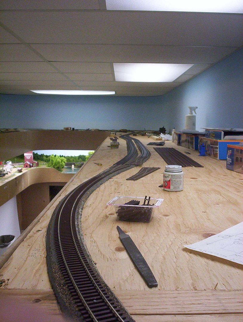
Here’s a couple:
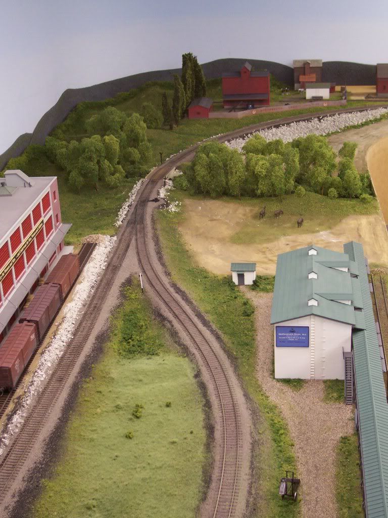
…and a couple more…

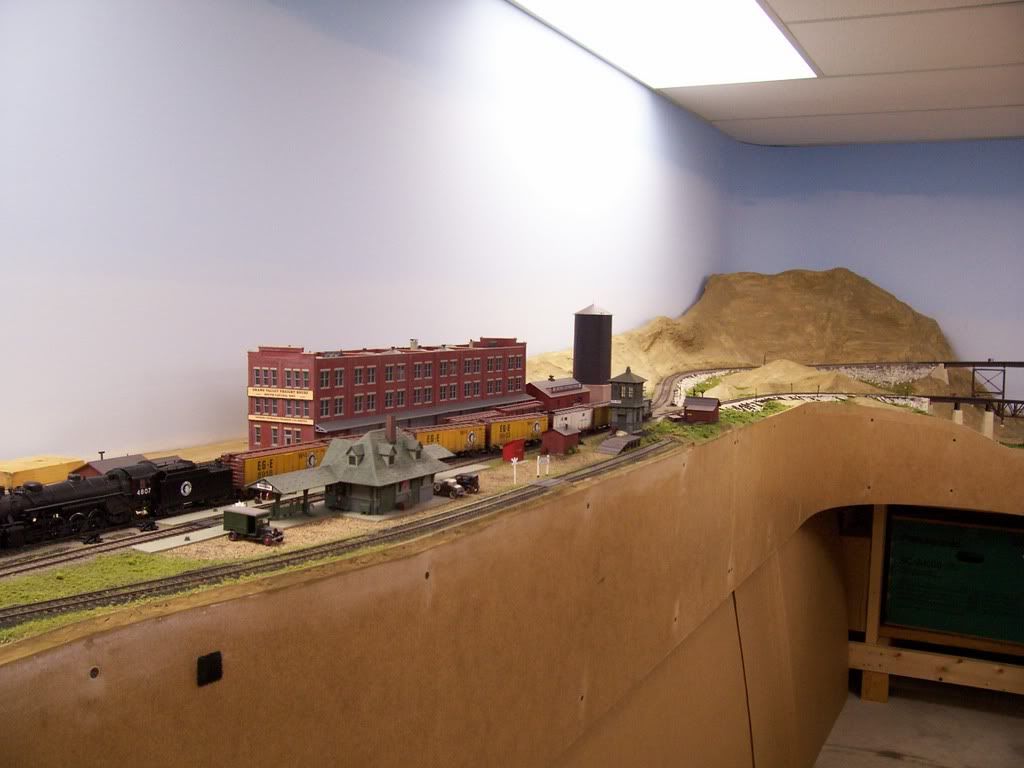
…and another:
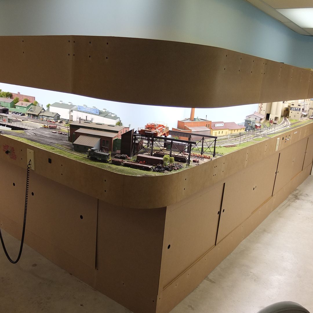
There’s another one here, partially visible between the tower and the handcar shed which is close to the layout’s edge:
I don’t bother putting a straight section between the curves - it wastes space and also spoils the scenic effect of a train snaking around it. While most of my freight cars are under 50’-or-so, I also run full-length passenger cars. The latter look a little odd on the tighter curves, which includes most on the layout, although none on the mainline under 30", but most of the layout has speed limits of 30mph or less.
Of the ones shown (there are a few more, for which I don’t have photos), the only ones with radii of known values are shown in the second photo, at 48" for those on the near side of the bridge, and 40" and 39" on the other side of the bridge - the 39" portion spirals down to 34" to curve around the end of that peninsula (the bridge is curved at both ends, but the centre portion, which separates the upper and lower S-curves, is straight - not, however, in consideration of the S-bends, but merely because it was easier to build it straight). Most of the other S-bends on the layout will likely have 34" or 32"
The radius of the two S-curve segments is going to be dictated, at least in part, by the length of the S-curve.
I have two S-curves on my double track mainline, one where the mainline wraps around my downtown passenger station and the other running through a pair of double track truss bridges due to a wall in the way.
Each S-curve is 8’ in length and the radius of each curve is 32" on the outer track and 30" on the inner track.
It seems to me that shorter S-curves are going to require tighter radius than 30". In my experience, once you get tighter than 26" radius, problems arise with derailments, especially at higher speeds.
Rich
The snakewiggle down the canyon between the only two JNR stations I’ve modeled doesn’t have a millimeter of pure tangent. What it does have is spiral easements that connect at the point of actual tangency. Radius varies from 24 inches (610mm) to (instantaneous) infinity and back - several times. The sharpest curvature is either on bridges or in tunnels, which is true to the prototype I’m following.
The new second track, currently under construction using the most modern equipment available, is tangent - and mostly underground. Bo-o-o-ring!!!
Chuck (Modeling Central Japan in September, 1964 - including a TBM)
The exact radius can be determined by the coupler overhang which is equal to (overall length minus the wheelbase)/2 and the allowable coupler side motion Which would likely vary a bit from manufacture to manufacture. I’ll crank out some math at lunchtime tomorrow.
Ray
I’d suggest that a nice flowing S need not to be too tight to get that visual effect but as you asked for a number I’d go along with Richs’ 26 inch radius. It’s what I used at the Club and it worked well with a variety of rolling stock, some indifferently maintained.
Now to make it more visual, how about some super elevation?[swg]
[2c]Cheers, the Bear.
As Wayne has shown if you use flex track and have a natural gentle easment into and out of the s curve you won’t have a problem at all even without a straigth section. If you are using sectional track with no easments then you will need a straight section between the curves.
Steve
I am using flextrack. I am also using laminated splines to make this section so the curves will flow nicely. I can’t reliably bend the splines tighter than about 30" without them popping, so based on what I read here I should be fine.
It’s interesting that so many have rejected the advice from Armstrong’s TPFRO without penalty.
Thanks guys for sharing.
How are the splines going. I had started to use them. All was going well until I decided to make a change to the layout. I ripped it out and am going back to cookie cutter plywood. I feel it is easier to make slight changes with the plywood vs. the splines. I also had trouble getting a continuous curve, I was using 1" wide X 1/4"thick masonite and woud end up with slight kinks where ever I had a butt joint.
Steve
Not at all as well as I had hoped. My original plan was to use them for most of the layout so I had a 4 sheets of 1/4" tempered hardboard cut into 7/8" strips. When I bent them down to the 24" I needed for my turnback curves about 50% of them snapped. I switched to cookie cutter for the rest of the layout. This one section where I have large radius sweeping curves is an opportunity to use up some of the supply.
I tried wood splines on an earlier layout years ago and found that they didn’t bend evenly. My experience is that the tempered hardboard makes smooth curves.
I use 1/8" hardboard ripped down to 2" x 96" strips for roadbed spline. Bends down to 18" without an issue, as long as you’re careful. Thirteen rows wide (7 strips, 6 spacers) is enough to support a line of cork roadbed. If anyone sees fit to go down this route, I’d suggest robbing a clamp store…
Stu
Bear, the twin S-curves separated by the bridge are superelevated, and with the cut-out 3/4" plywood used for the sub-roadbed, it was easy to transition that superelevation through the esses, too. All of the curves on the lower level of the layout are superelevated to some degree. It’s strictly for appearances sake though, as almost all of the track has speed limits of 30mph or less.
While I didn’t use spline roadbed, 1/8" Masonite is probably the easiest material to use for the splines. There’s no need to spend extra for “tempered” either, as my independent lumber dealer informed me that the “temper” refers only to the hardness of the outer surface. I used regular 1/8" Masonite for all of my coved corners on the backdrop and all of the layout fascia, too.
The curve on the lower fascia in the photo below is an 8" radius:
You can make serviceable clamps by cutting squared-off “U” shapes from 3/4" plywood. Bevel the top inside corners of the “U” slightly, and then tap them into position with a clamp or two temporarily holding the splines together. Move your limited supply of actual clamps along as you work, taking care to not accidental
I thought about that, but eventually you get to the point where the splines are just forms for the glue. [:)]
I too have quite a clamp collection.
Yep. 1/8" hardboard figures prominently in my fascia and backdrop plans.
I have never had any success trying to add splines to the curve more than one at a time.
13 layers at 2" tall is going to take a lot of glue and time. In the end it is probably the best way.
with the 1/4" by 1" tall I spent the whole winter glueing splines together and it did not turn out as I expected.
Sorry for going off topic.
Steve
Not sure people rejected that advise so much as simply didn’t need it. I was thinking TPFRO needed to be mentioned, so was already reaching for my copy. Looking at what Armstrong wrote, he basically gives a universal rule of thumb that you leave one car length (of longest car to operate over the track) between curves. Unlike many of his other standards, he gives no other formula to adjust it according to curvature.
Of course, what people seem to conclude is that at higher radii the need for the car length fades because what side to side difference is within the swing area of the coupler and its draft gear. Ultimately, it’s that parameter that is the crucial one, because once the travel limit is reached, then you get the binding that leads to derailments that led to the one-car-length rule.
Back to the OP’s question of an “S” curve for 50’ cars, I cranked through the math based on some measurements of coupler swing for an HO scale blue box car upgraded to Kadee couplers. With a 3/16" sideways coupler swing and no transition easments, the answer is 27 inches. Anything tighter than that and the couplers will bind.
Ray
Thanks Ray. I love math based answers.
There is a guide out there where someone tested a lot of combinations with different length cars (can’t mention the publication as it got deleted by moderator early in this thread). They tested most combos and found out in some cases S curves don’t mater, depends on length of S curve, what you are running and a few other factors. On my layout where 40’ boxcars are the norm, back to back 18" radius are fine over a 18" length in HO.
Note that was “tested” by using only two cars and gripping one in the middle to move them through the curves. The build-up of forces is different through the couplers when it’s cars in a train. (Especially when shoving or when using mixed-length cars)
To the Oriignal Poster: if it were me, I’d use a straight track between. But since you don’t want that, I’d suggest easements, at least, between the curves. That would look more realistic and accommodate slight imperfections in construction.
… and I’d certainly mock it up and try variations of car lengths and locos pushing and pulling. But I’m a belt-and-suspenders kinda guy when it comes to reliability.
Byron