Hi
What size styrene would I use to make the under frame? It 's that center beam that runs
down the middle of a freight car.
&nb
Hi
What size styrene would I use to make the under frame? It 's that center beam that runs
down the middle of a freight car.
&nb
Depends on what you’re building. What’s the prototype use? Then figure out how closely you want to follow that in building your model. Real-life often presents problems when scaled down because it is difficult to have model materials realistically thin. They become fragile and difficult to work with.
Every model is a compromise. Do the best you can with the first one, then do better on the next, etc, etc repeat as necessary.
It could well be that simply using a solid piece of plastic is the way to go anyway. If I was getting started, I’d recommend making the stuff you can’t see, but which need to be as square and true as you can get them, as simply as possible. Don’t start by building a super-detailed underframe. You might get discouraged and quit before you get to the parts you can see. Instead, build your frame, get trucks and couplers on it to test, then proceed with the rest of the car as best you can.
You’ll find that a challenge, I’d almost bet. Then concentrate on building the visible body of the car, which will likewise be a challenge. If you get a decent finished car out of it, you’ll be on top of the hill, but already starting to see ways to improve. Even if you don’t, you’ll be close and convinced the next one will work. Then you can switch to building a detailed underframe once you have the more visible parts under control.
Mike makes some good points, but if you’re determined to build a model of a real car as close as possible in scale fidelity, you need to know the type of frame used and the dimensions of all visible underframe components. Even then, about the thinnest material you’ll find, at least in styrene, is .005" sheet - roughly equivalent to 1/2" in HO scale. Unless you’re planning to work in brass, I’d suggest an immediate compromise, and that you opt for what’s available in Evergreen strip - they have a wide selection of strip, with the smallest dimension being .010"x.010", with one or both dimensions increasing in .010" increments. Also available are strips in HO scale dimensions, such as 1"x3", 2"x4", 2"x6", etc., and a range of structural shapes - angles, channels, I-beams, etc. Most of the smaller dimension structural shapes scale-out much thicker than the real ones.
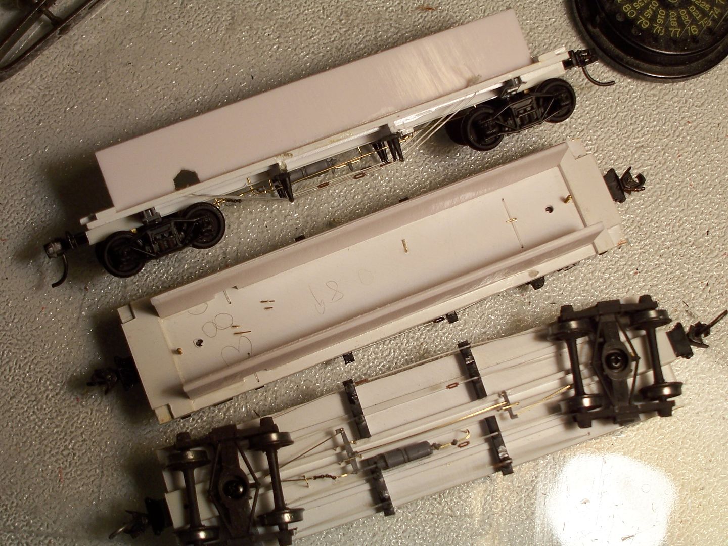
Using a to-scale underframe may yield one with little structural strength, but if the basic floor on which you construction the visible parts of the car’s underside is of substantial material (I use .060" sheet styrene), you can add in-car stiffeners (again. .060" sheet material, on-edge, works well and is inexpensive when bought in 4’x8’ sheets). Here’s a photo showing floor/underframe assemblies which I made for some shortened Tyco reefers which I converted into 36’ truss-rod cars:
Here’s the original car, with the sagging floor which was the impetus for the re-build:
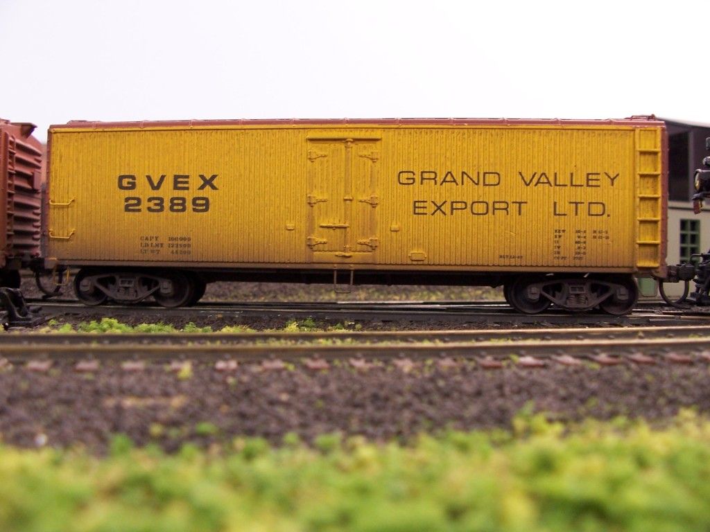
…and one of the four rebuilt versions, probably as close to scratch as is possible for me using a commercially-available train set-type ca
Hope you don’t mind me butting in Chris, but could you please tell me what thickness monofilament thread did you use for the truss rods doctorwayne?
Thanks and Cheers, the Bear.
Well, I couldn’t tell you the “test” of that line (it’s on an old reel which I used as a kid) but my calipers show it as being about .012" in diameter.
The idea of using monofilament is to allow a continuous truss rod (stronger than a separate piece coming into each end of the turnbuckle), while still leaving the centre of the turnbuckle looking as if it’s open. It’s not my idea, and, unfortunately, I don’t recall where I saw the magazine article or the name of its author.
Here’s a better look at the arrangement on a modified MDC underframe - the turnbuckles (Tichy or Grandt Line) are not yet centred nor cemented in place:
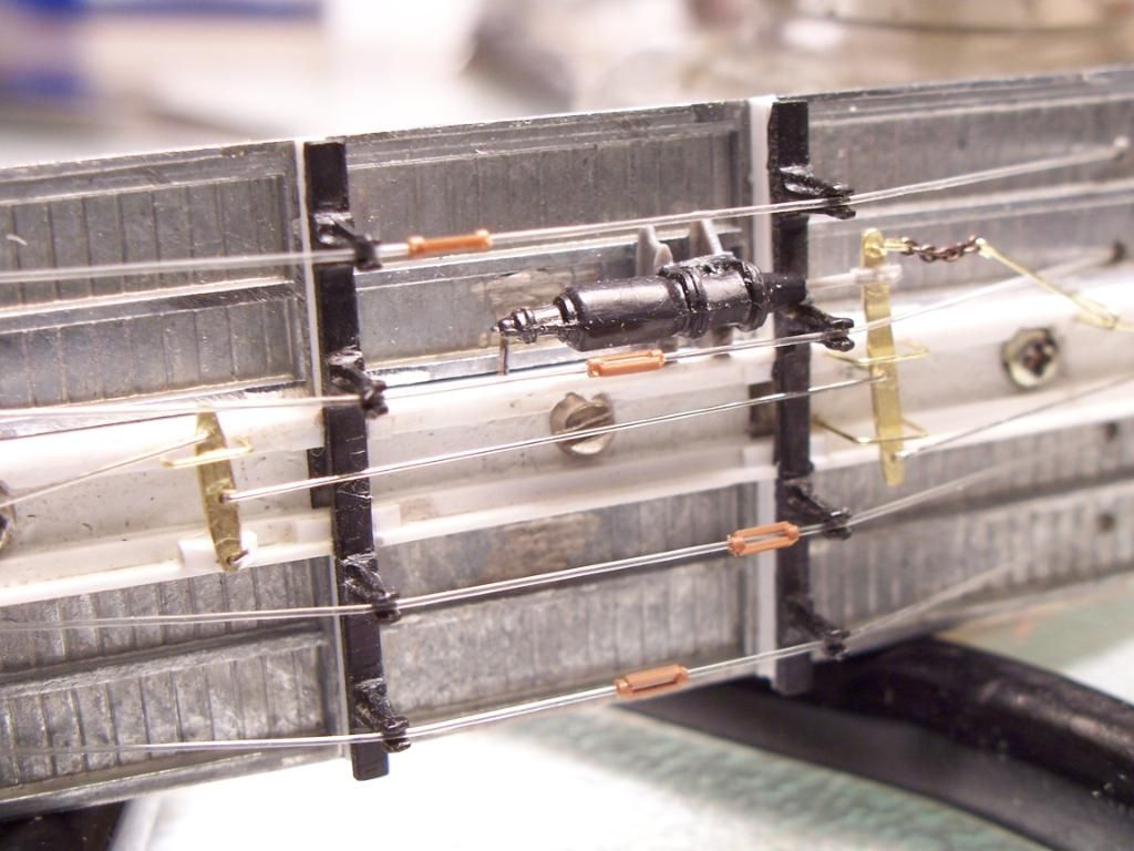
On the top side of the car’s floor, the line is wrapped around a piece of sprue, with a couple of knots and some ca added. The free end is then fed through the hole in the car’s floor, a turnbuckle slipped onto the line, then it’s fed through the applicable hole and back onto the top side of the floor. There, it’s routed sideways to the next position and threaded through, the procedure repeated until all rods are in place, with the end tied-off as in the beginning. During this threading process, all of the lines on the underside of the car are lying flat on the floor and are pulled fairly taut. To remove most of the remaining slack, I slip spacers (they’re short lengths of strip styrene in the photo below) under the cross-over portion of the line, as shown below:
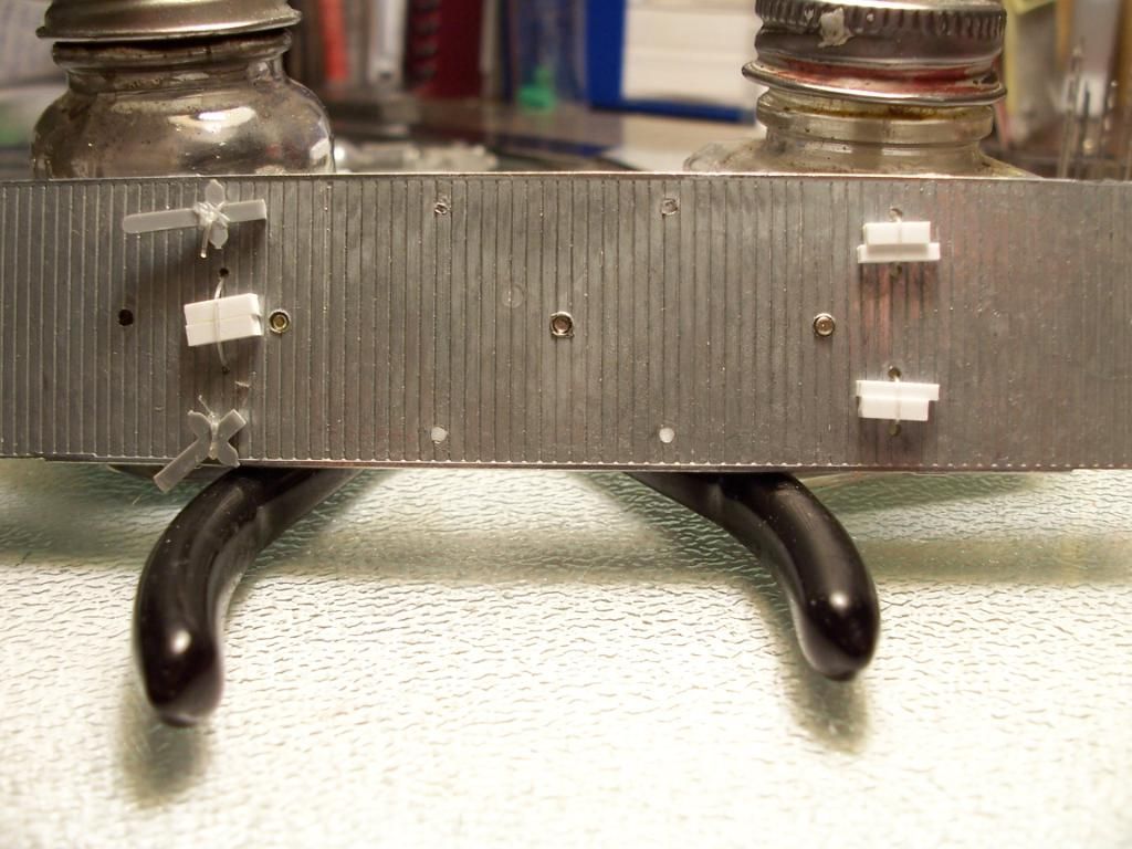
These spacers are simply held in place by tension, and may be removed and replaced with thicker ones should the line later stretch and start looking sloppy. Finally, the lines on the underside of the car are gently lifted into place onto th
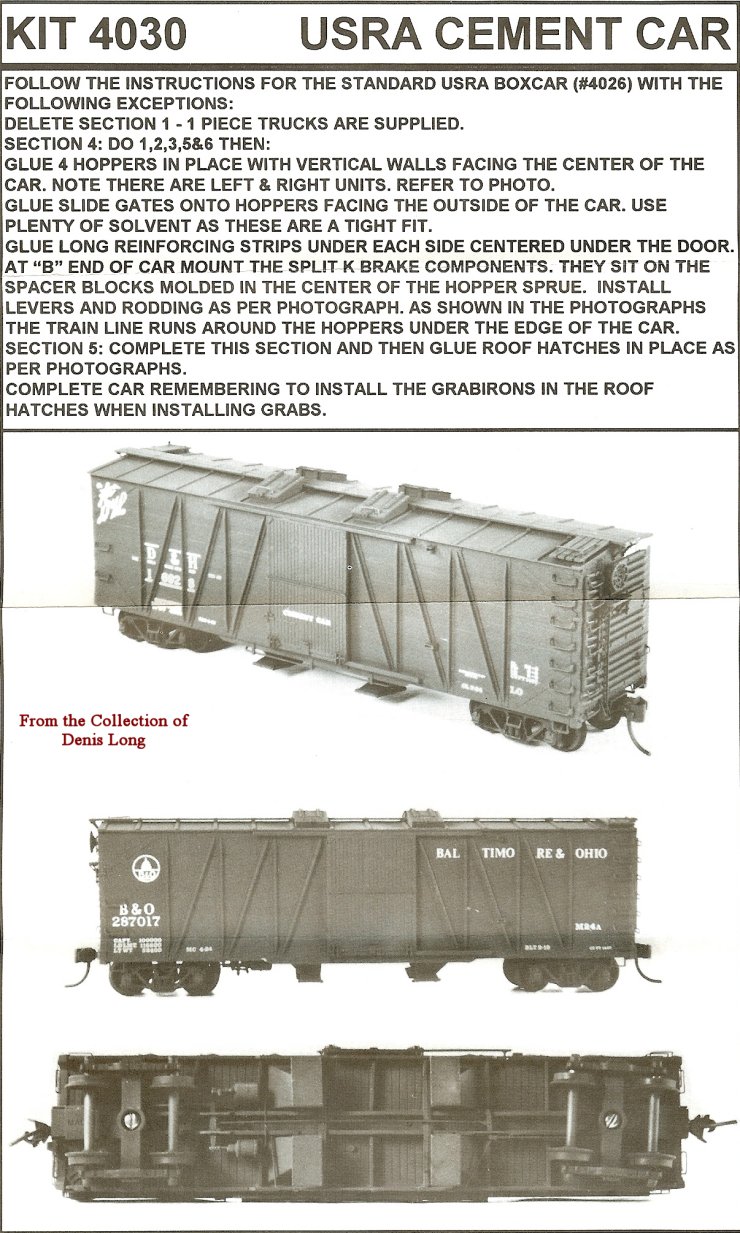
Gidday Chris. just measured one angle of the two beams that make up the centre beam assembly on a Tichy freight car kit ,shown here, courtesy of Hoseeker http://hoseeker.org/tichy/tichy4030usracementcar.jpg the angle measuring .136" x .039" x.016". I certainly would not suggest that you adopt those measurements. [:)]
doctorwayne, many thanks for taking the time, didn’t even realise that there were such things as HO turnbuckles, and here I was thinking of using cotton a’la the Roundhouse “shake the box kits” and a dab of glue to simulate the turnbuckles. [:-^]
Cheers, the Bear.
Both of these I built a long long time ago from wood. They were built from plans published in Model Railroader. The roofs and floors are milled basswood, still available from Northeastern. Siding was scribed basswood on the wood car and a glossy photo print for the steel car. The ladders and air brake parts were from the junkbox. Decalling was done before I learned about Solva set and DullCote.


In answer to your question about size of the center sill. Try and find the dimensions of the prototype, from plans, drawings, photos, MR articles, personal observation. Once you know what the prototype used, any material that comes withing 10% of the prototype dimension will look alright. For prototype photos, Google is pretty good about finding them. If all I have is a photograph I draw my own plans full size, and figure out the dimensions from comparing the size of things in the photo. For instance freight car wheels are 33 inches, people are almost 6 feet.
If you are building a flat or open top car, I would consider using brass shapes to build the center beam to gain weight. Other common techniques to add weight are to put a metal sheet between the underframe and the deck.
One drawback to a metal underframe or even just center beam or weight that is screwed into by the truck and coupler screws is that the combination of metal from one car end to the other, all metal trucks (also good for weight), and metal couplers (Kadee #5 and versions like #58, #148, #158) can create magical electrical short circuits. And the shorts can start or stop by coupling and uncoupling!
At the very least, the couplers must be insulated from the frame - meaning a plastic post and coupler box. Even with insulated couplers, the metal trucks must have all wheel sets with the insulated wheel on the same side.
just things I have learned [:$]
Fred W
Even better for a brass or other metal car are double-insulated wheelsets. We can get these in HOn3, but I’d think should also be available in standard gauge. Another trick is to use plastic trucks when building brass.