I’m looking for any MR examples out there of piping from a factory extending over rail lines to the other side. I need to have some piping -like a pipe bridge - extend from my paper mill over the mainline and siding (2 tracks total) to the waste treatment pools on the other side, next to the river. Does anyone have any example, or know of any kits for the piping that would would work?
Or I guess I could “underground” them under the tracks. Any prototype advice?
Depending on the size and length of the pipe, it could be self-supporting (think of a frameless tankcar), but it would probably be more visually interesting with some sort of a structural steel support. In the photo below, there are multiple pipes, and even though they span only a single track, I felt that they looked better with the support structure. Rather than try to form a curve where the pipes transition from horizontal to vertical, I simply filed the ends of the vertical pipes to match the curve of the horizontal ones. My story, if anyone asks, is that the end-plates are for clean-outs. [swg] The pipes are styrene tube and the support structure is styrene structural shapes - both are from Evergreen.
Here’s a view of the bottom end and part of the tank car loading facility. I didn’t bother to use structural shapes here, as this area is not normally easily viewed.
Google “oil refinerys”. At the north end of the NJ Tpke, there are lots of oil refinery/depot places and I’ve seen many pipes going over the tracks - usually attached to signal bridges and road bridges. Sorry, I don’t have the guts to stop & take pics for you!! Between Homeland Security & traffic, I wouldn’t last too long!![8D]
Doremus Avenue in Newark has several pipe ‘bridges’ along it’s path - large ones, too.
This Live local link takes you to a decent sized series of pipe structures.
Move around the Doremus Ave view - there’s some interesting pipe structures there.
Oh yes, don’t forget This kit as a source of nicely formed piping to route thru your pipe support structures.
That Walther’s kit is exactly what I was thinking of when you asked your question, assuming it’s not vapor ware and actually shows up in January, I think it would be worth the wait. It looks like it has plenty of pipes and would be very easy to kitbash to different heights. Even though sprues are free, I think this kit at $12 would be well worth it.
In my travels as a truck driver, I’ve been to many industries where pipes are “bridged” over rail lines, roads and driveways, and sometimes even over waterways. Occasionally, the pipe is strong enough to support itself (especially for short distances), other times it may have quite the support structure (sometimes to the point of overkill). Perhaps the designers were anticipating future additions.
I’d simply use whatever Plastruct, Evergreen, Micro Engineering, and whatever else to build a suitable structure.
What do you want to achieve with the overhead pipe(s)? Is it just a link between factory parts or are you using it/them to hide something… like where your trains go “off scene”?
Okay, these ideas may not apply to you… but someone out there may like them…
I love pipes over trrack to both hide scenic breaks and to add variety to the otherwise ordinary.
Most of the ideas can be used both ways.
Something we see here and I’ve seen pics of for places like the NE corridor (pretty urban bits of RR) is pipes emerging from the side of a cut or trench, crossing the track and back into the ground on the other side. With a cut this is sometimes an arch of pipe. With a (masonry lined or similar trench) it is usually a straight pipe. In almost all cases in an urban situation the pipe itself or the end area is usually fenced with steel railings or spikes. Sometimes barbed or razor wire is added if there is a particular problem. Despite this the grafitti people still get in if they can.
Sometimes these pipes are on their own, sometimes multiples (not necessarily the same) and sometimes they are adjacent to a bridge or tunnel mouth. I especially like them around tunnels as they break up the routine way of going off-scene.
The great thing with these pipes is that they are frequently utilities (gas, water, sewage, drains) so they don’t need any industry or other explanation. I’ve seen them from 6" to 4’ diameter. The smaller ones are often flanged at the joins while the big ones appear to be continuous so are probably welded.
There’s proably structural reasons why the smaller ones tend to be supported while the bigger ones are supported about 50% of the time while 50% are self supporting.
Just thought… an interesting thing to add in one way or another is a cage round the pipe enclosing a valve. Some places the valv
You have say a 24" main pipe supported about every 15’-18’ on steel cradles set on concrete plinths. About every 5th/6th support is a double cradle or a brick inverted saddle. This pipe (for the sake of it) is going to be a dulled black going grey. It is not lagged but has been wrapped in a protective fabric (like hessian sacking) around wet bitumen with a bitumen top coat added. There are clear black squares of repair patches in places where the coating has decayed/cracked/been rubbed by shrubs.branches mocing in the wind (big weeds… may have been cut down to stubs/stumps… hardly anyone roots them out even though we all know they will grow back).
With all this detail to add you want some length to work with so this pipe is going to follow the track - let’s say outside a curve.
There’s a grade crossing… because the local truckers kept hitting the arch-over the pipeline owners are switching from up-and-over the road to underground.
We’ll leave the pipe rising at about a 30 degree angle on increasingly long steel legs (so why didn’t the truckers see the pipe?) and we’'l have all the height warning markers in place. The pipe can cross the road with a big I beam (say 6x12) each side for support and a smaller sacrificial beam bracketed off the most hit side… complete with dents. (Can’t have a truck stuck into/under it as this would shut the RR… could have a cop/patrolcar stopped a truck just short…)
The Utility Company/ Township-City and RR have got fed up with bridge strikes so we can have construction work at some stage of progress digging out the s
One rail location I work has brine fields each side and pipes all over the place…
Due to the nature of this area the track is mostly on fills and roads, pipes etc go under through (mostly) very low bridges.
Some of the pipes get together in clusters and run alongside roadways, track or both. There are usually mixes of 12" and 36" pipes. (I don’t have a clue why). They are mostly on steel legs on concrete plinths. The bigger pipes’ legs have cross braces. The pipes are generally side-by-side… but at places they switch to being stacked… this happens more often where they get together to squeeze under a bridge leaving vehicle access on one side… only cars or pickups due to height. At some places the pipes swap psoition in the side-by-side setup… this is always an up-and-over never a down-and-under or a 50/50. Sometimes the switch in position is achieved going into/out of a vertical stack.
I don’t have a clue how they work out where/why they put the assorted valves that stick out from place to place. They don’t always appear in clusters.
All this may give some ideas.
A variation I would consider would be a bunch of pipes on the surface/coming out of building(s) and wanting to cross the RR where the RR is at grade with the surrounding factory land.
Instead of going over or just vanishing into the ground I would create a concrete pit rght through under the RR with a steel or concrete (depending on era) deck bridge across the middle. The pipes would turn 90 degrees down into the pit, cross the floor - may or may not have supports - and climb out the far side.
The pit could have either steel ladder access or concrete steps… maybe different each side. These days it would be fenced off within the factory. An older pit would usually at least have railings round it.
There should be a sump in the pit and some arrangement to drain it
Yet another place I have worked most of the assorted pipes - very assorted - and lots of cables are in a concrete conduit system underground. (As this is a 1960s system the tunnels are squared and just below the surface but modern factories tend to go deeper and use a boring nachine to cut a round tunnel).
The system shows on the surface as a number of types of entry points…
concrete panels set in roadways. These are about 2’x3’ each extending in multiples of 2’ in the direction of the conduit which doesn’t al;ways match the direction of the road. The rarely used ones have the joints filled with pitch while the regular use ones are pretty battered. When these are open they have red/white guard rails and cones put round them. Most of the “pits” have a steel ladder or steel rungs fixed in the wall.
there are a couple of doors in the sides of buildings that are labelled as access routes to the system. Inside there is a vertical steel ladder on the back wall (away from the door). there are all sorts of regulatory signs on the doors.
There’s a corrugated metal hut in the middle of a green space. this has a stairway leading down into the system. It also has the blow-off vents from the steam lines sticking out of the top and is often half hidden by a cloud of steam.
To one side of the site there are catch pits for rain and any other run-off. These must link to all the drains on site which have some connections to the conduit system… although i don’t know what. (I do not want to go down there)!
I know that there are various pump systems in the depths. Occasionally a pump gets lowered in and the old one hauled out.
This sort of operation could be modelled on the surface. Apart from the red/white boards there is usually an A frame assembled with the hauling gear. There is usually also a pickup parked nearby with the to
Where there are multiple pipes around a factory they are often colour coded (there is a standard code). If the whole pipe isn’t coloured they will have code ed areas. There are often flow direction arrows on pipes. Any lettering is often close to or between flow arrows.
Smaller pipes and cables are often laid out flat/side by side on metal racks like small Pressed Steel Planking. This “PSP” may be fixed flat or on edge on support poles… often the ones used to hold up pipes…
Through about the 1960’s, if the pipe bridge was too low to clear a man standing on top of a RR car, it would have had to be protested with telltales. They were vertical pieces of rope that would hit and thus warn anybody riding the top of the cars that a low obstacle was coming up.
Such structure would be a great additional detail to add.
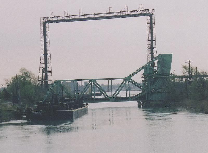
I know this is supposed to be about pipe bridges over railroads, but how about a picture of pipe over a ship canal:
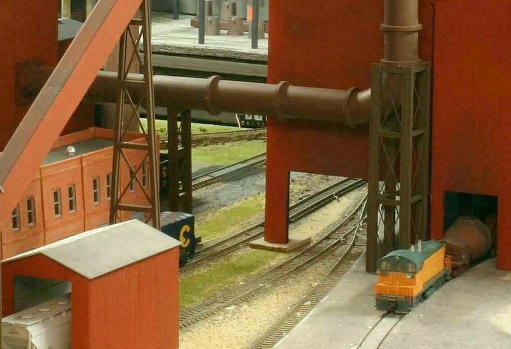
Here is a modeled example of a pipe large enough to be its own bridge - a ‘downcomber’ from a steel refining furnace. It is supported in the middle by a pair of heavy H-beams.
Just wanted to thank everyone for their excellent input here; I was away for much of the weekend and am now just catching up.
I’m going to try my hand at one of the pipe bridges with this input and the photo references. It’s a pipe from a paper plant over the tracks to the wastewater treatement pools on the other side, near trhe river. I’m going to make the pools with PVC pipe and some walkways. I’m not going to “underground” the pipe system since i guess it’s unlikely that in tjhe prototype, railroads would let/have pipes running underneath their roadbed.
Perhaps not what you’re talking about, but there’s a pipeline running parallel to some now little used or abandoned trackage between Minneapolis and St.Paul (former Milwaukee Road line I think?) where the pipes use the old railroad plate girder bridges to cross some streets.