I was doing some thinking recently about ops on my layout. The emphasis has been on the Silverton Branch. Then it shifted to what turned out to be a rather significant addition, the Cascade Extension. It almost doubled the mainline length of the narrow gauge, but its 20" min R limited many locomotives from operating. I did some work on several problem areas of my track and tended to some issues on various locos that held them back so they could operate on the Cascade Extension.
One issue was the fact that trains from Durango had to go past Tefft, where the extension took off from the main, to Silverton in order to turn on the wye there, then enter the facing point spur after they left Silverton. This backtracking could be the sources of confusion over the East vs West direction of the train, give it amounts to about 6’ of track.
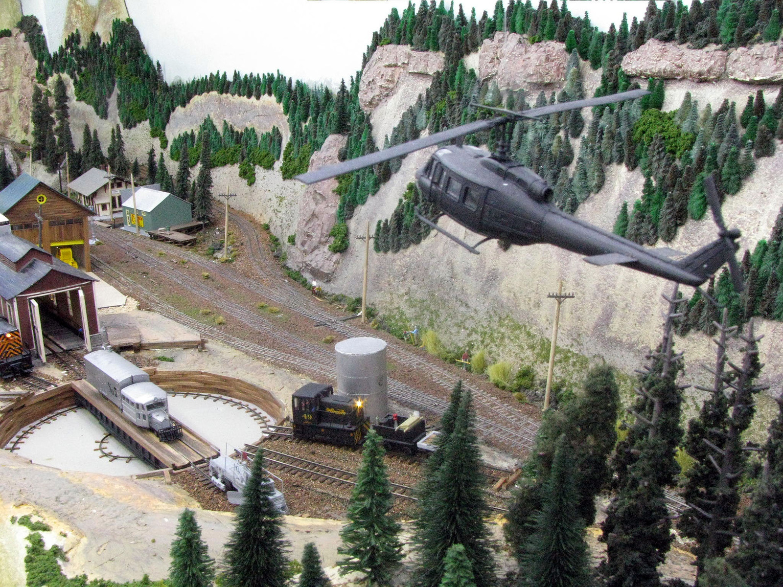
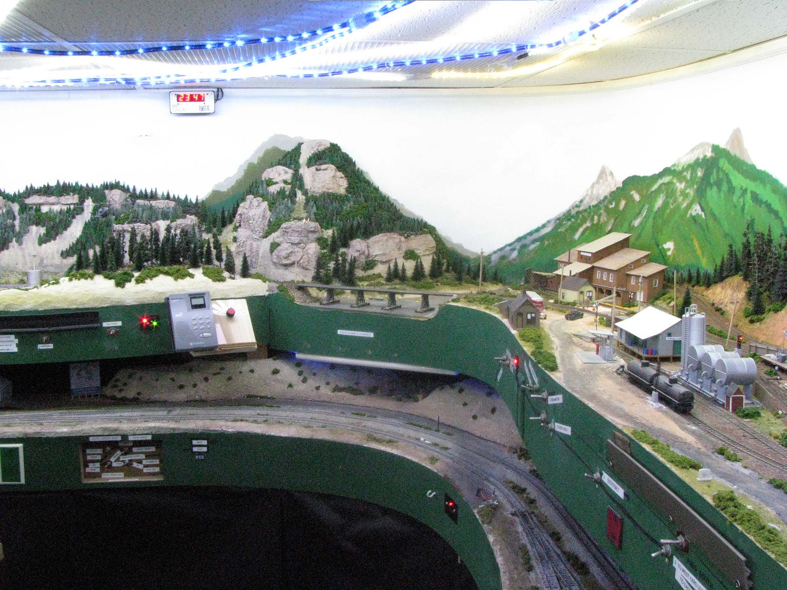
Here’s a pic of where the Cascade extension diverges at Tefft and heads uphill, timetable West, even though it backtracked on this stretch of track eastbound after going to Silverton to turn.
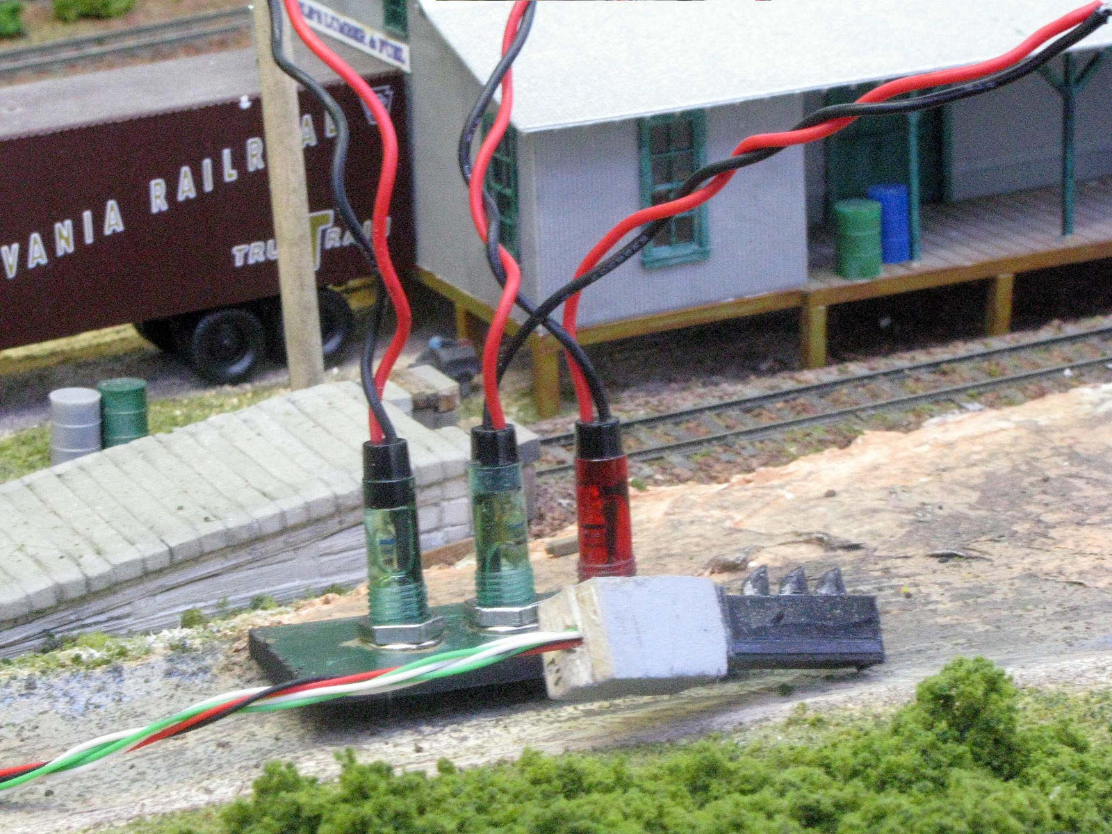
I used some SMD LEDs from Radio Shack (276-0321 Red and 276-0322 Green) to build the signal heads. For the repeater signal panels on the fascia, I used the 276-0271 Green and the matching Red LED assembly with a built in resistor. This set has two greens in it in order to show both the main back to Durango or the diverging route up the extension.
The two assemblies are wired back to back in series. Changing the polarity of the circuit lights one or the other color. Only two wires are needed for connection to the switching arrangement for the signals.
The signals were built from pieces of Plastruct H beams and other bits of plastic tubing, etc. The light from these LEDs is
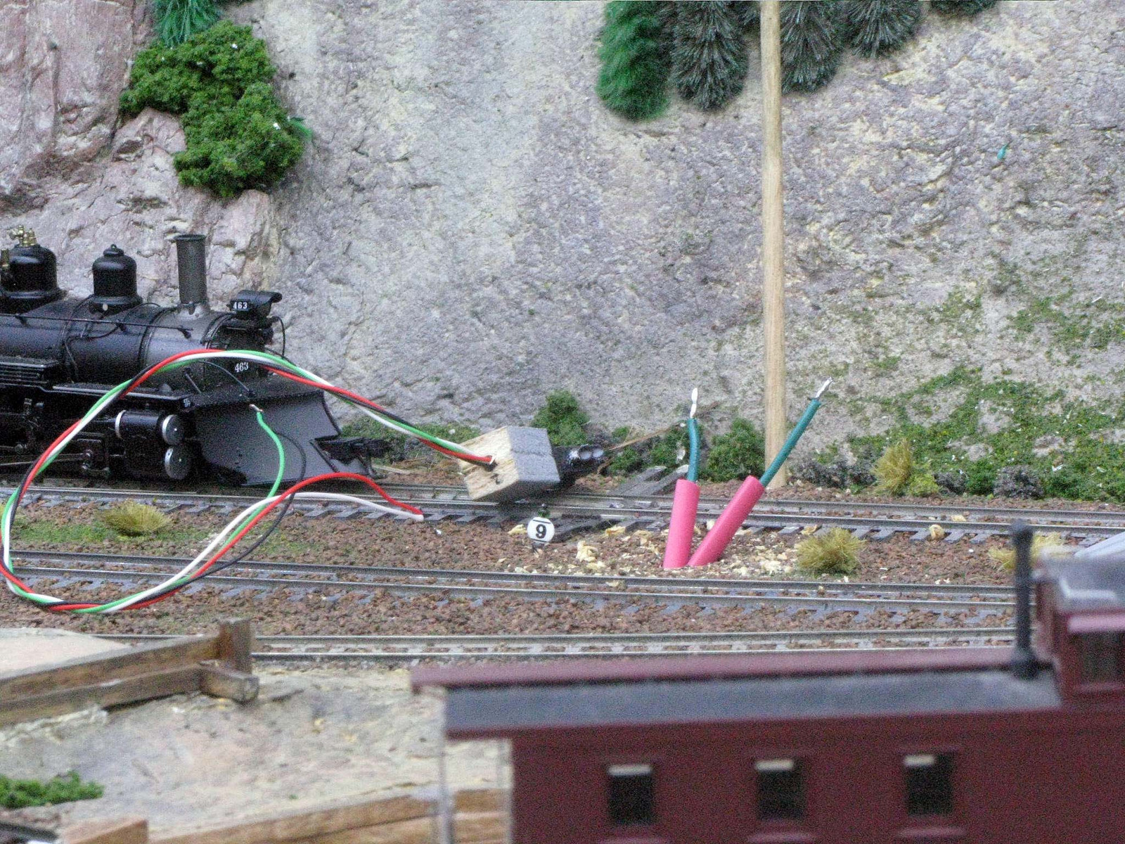
After building the signal heads, I shaped some balsa as a base. The Silverton line gets lots of snow, so even though I liked the ground-mounted dwarves, I felt they needed to be off the ground. Here are the main (on the right) and the branch (on the left) signals at Tefft. The short stretch of track between the main and branch signals on the branch is intended to shelter a helper engine, the Goose or other short train for the dispatcher to keep trains rolling by on the main.
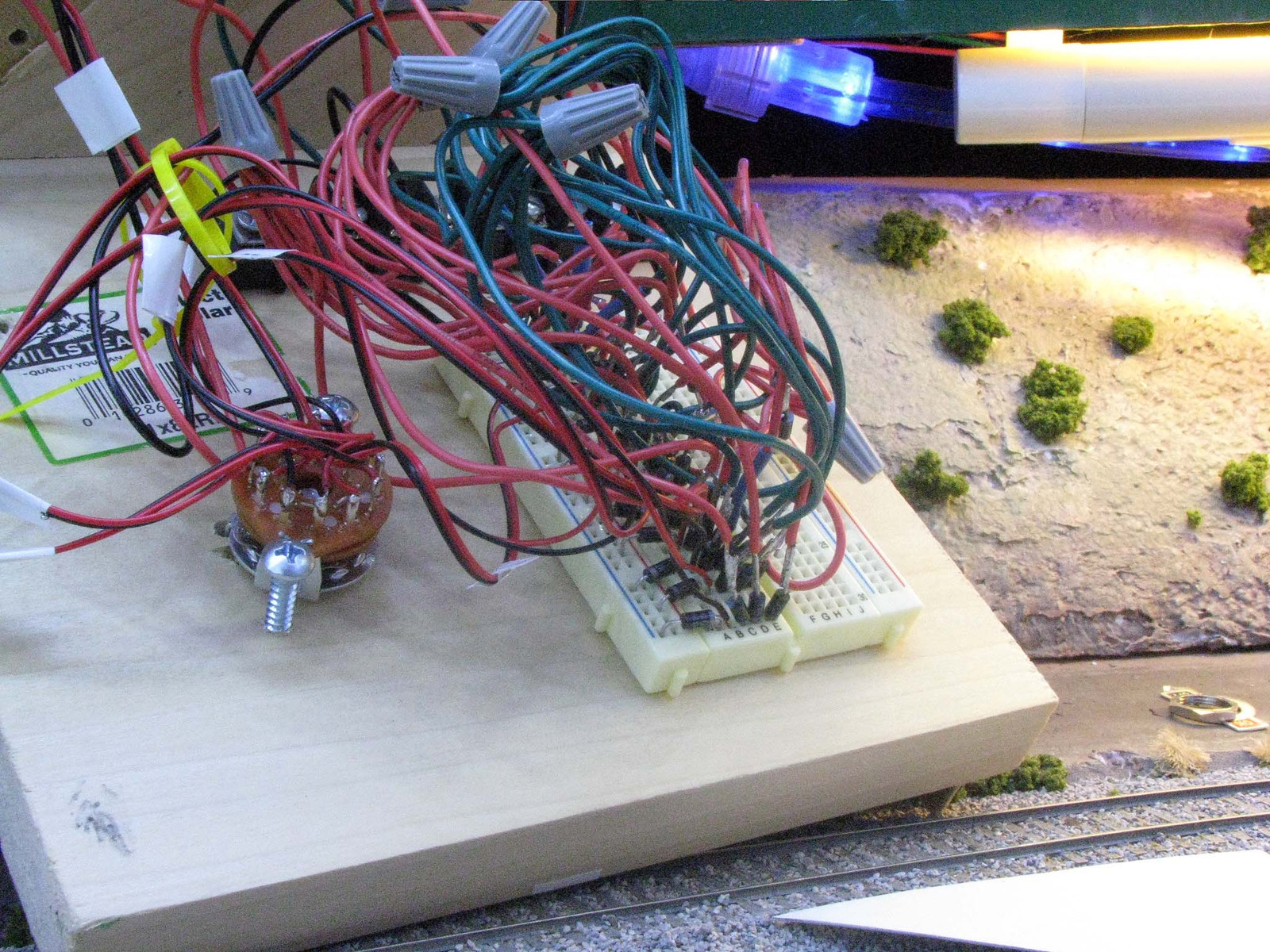
This is the breadboard shown more closely. I’ll add some pics of how it’s (sorta) organized later. Basically, I selected power to six circuit and set the turnout for Cascade to corresepond to the signal.
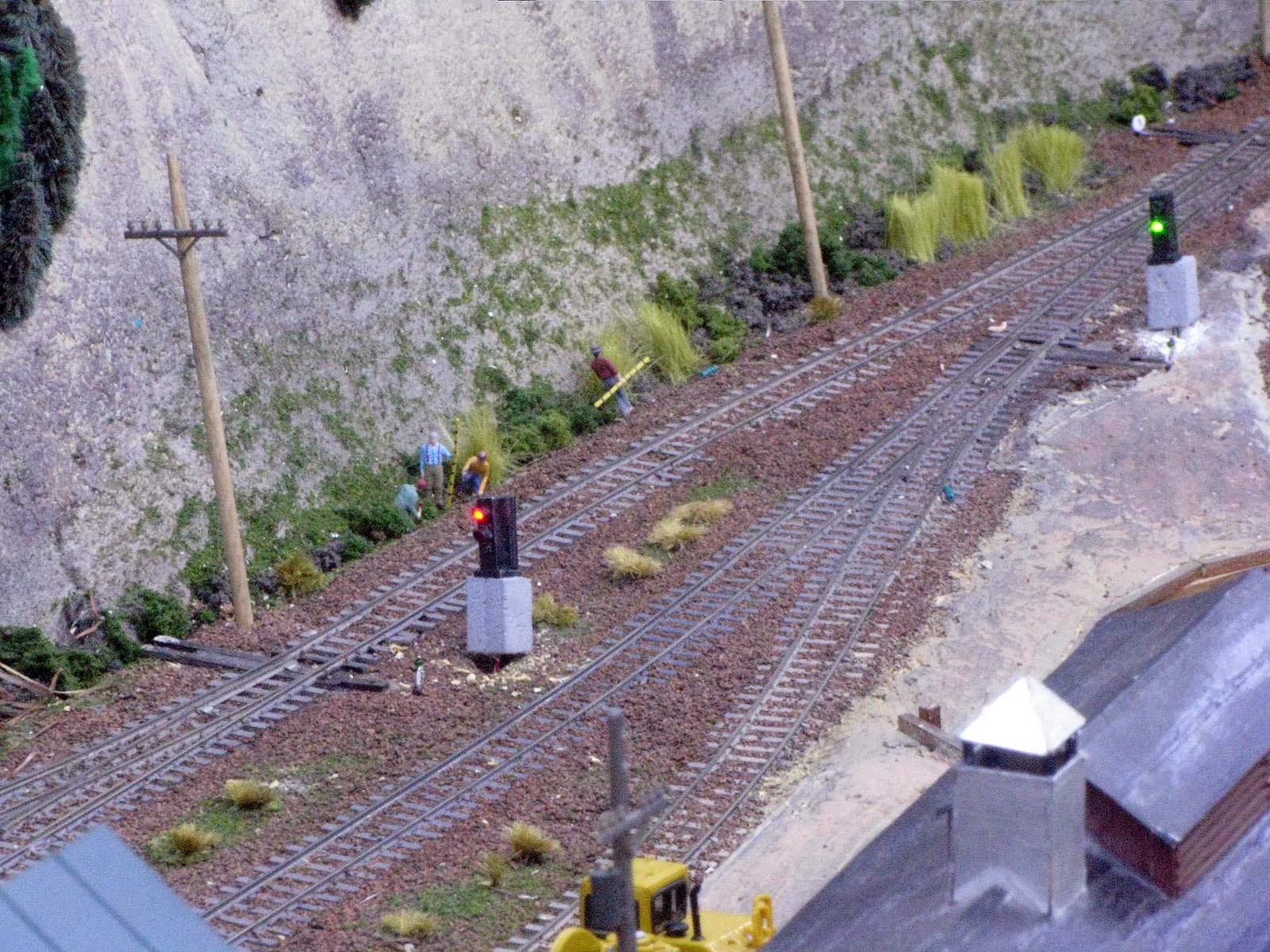
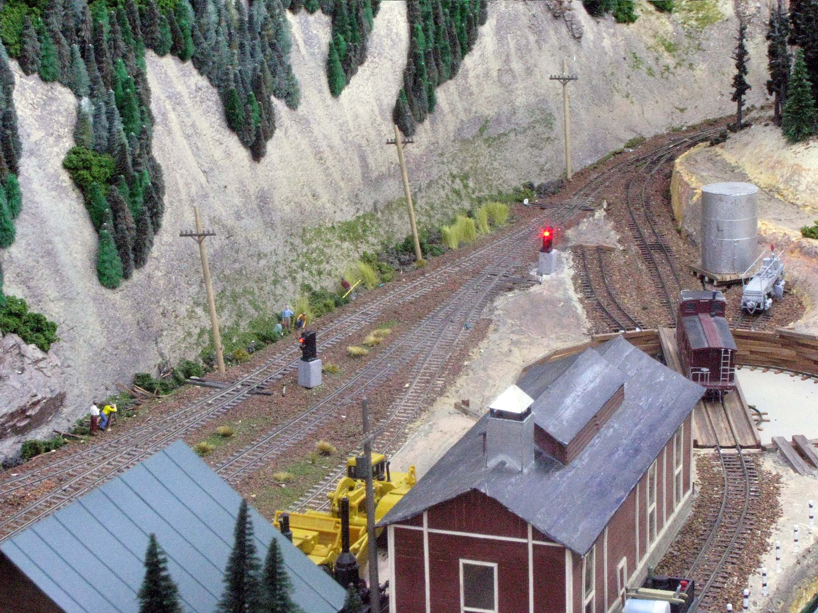
In the following pic, the signals protect the uppder deck line from the right to the left of the pic, from Silverton to the west swicth at Tefft. If no one dispatches, close enough to verify by sight and reset the “interlcoker” control to your route. If there’s a dispatcher, then he can be involved to authorize use of this section of track, with the radio readily available to use.
This pic shows the signals at Tefft once finished and set on their foundations.
Here’s what makes it work, although I don’t have a circuit diagram. What I did was draw up a logic table, then my wife (whose EE is in digital circuit logic) helped me refine it. Basically, the idea was to build my own “macro chip” on the breadboard.
Yeah, I’m not much on neat, but it works for me, and once I finished the case today, no one will disturb the wires. It would’ve taken several hours to go back, document the wire positions on the breadboarfd (which is labelled by row and column to make that easier), and neaten things up. I probably would’ve knocked something loose and spent an hour putting it right.
The concept is what is important. There are two vertical buses on each side of the breadboard, with rows of two pairs of horizontal 5-hole buses in between.
I supplied power for the Tortoise the machine controls along the left two vertical buses, + and -. The 6 leads from the rotary switch then went to 6 pairs of rows in middle.
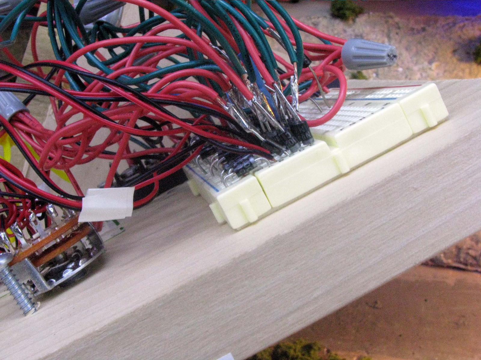
For the turnout power and to control direction, power from the switch was picked up by a pair of diodes that lead to the left-most vertical buses, six pairs.
Each of the three signal circuits (four in the #3 position to supply the second green LED for a diverging route) plugged into the horizontal row in pairs, with a properly-oriented diode on each wire to prevent sneak paths. When the rotary switch is turned to each of the six positions, it changes the polarity of each circuit to delineate the route through the interlocking. Looks a little messy, but the logic of the six routes is hardwired in place.
Here’s the finished panel, with a power switch for the panel on the right side, and the radio at hand to talk to the dispatcher.
Thanks! I wasn’t sure I was going to be able to solve the puzzle, but stuck to my troubleshooting skills – such as they are – to keep me going. For a relatively simple junction, it turned out rather complex.
The first couple of rows took a long time…I started thinking just a few diodes would be needed to solve a few “sneak paths” – then I realized rather than try to figure that out it was just easier to do them all than worry about sorting them out.
Impressive indeed. But question does come to mind: why the hassle of building it in HW if you have JMRI Running already?
Granted the SE8C is not cheap at $100, but you could control the turnouts and signals, plus have room for many more signals and add detection later as well.
But I really like it as a challenge. I had one like this on my prior layout, relays, diodes, panel indications, flashing LEDs, … Albeit I had only one of two routes controlled via two SPDT (mom) switches.
The answer to that question is that I wanted something that was idiot proof and did not require a dispatcher.
JMRI and I have a rather complex relationship. When it works, it’s great! When it befuddles me, grrrrrrr. Don’t want to be guessing which is which at any particular operating session. I just want something that is simple and can be depended on to function exactly as I intended it to.
This junction is also the only signal installation I can anticipate needing, at least on the narrowgauge. I could see signals on the standard gauge at some point, as they make more sense there. Technically, it’s probably not even an interlocking, really, more of an electrically-powered baton system. The real benefit here is it facilitates being able to treat the entire run from Durango to Crater Lake as continuous. I’m really not all that interested in signals, per se, more in what they can do to improve operations.
That is why railroads build interlocking towers. And ALL levers MUST be returned to the normal position after the train passes.
ALL interlocking signals are RED until the tower operator clears them. They can ONLY be cleared when the plant is in correct alignment.
Route of LION has levers for the switches and levers for the signals. Align the plant and then clear the signals.
The NORMAL position for each lever would fleet the plant for thrugh traffic on the mane lion.
You always KNOW that thing are in the correct position because the levers are clearly seen, and because railroad rules require that the switches be alighned to the normal position after the passing of the train.
That is just one of the reasons why it’s not quite an interlocking. There are more I know and I’m sure some that I don’t know that my signal experts are sure to tell me about (one is an ex-IC towerman and another helps teach the signals part of RR engineering at the big U – and that’s even before I get to my mostly model-rail signal consultants.)
Nonetheless, considering that no lives and little property are at stake – and given the limited area that allows full visual contact over all potential routes, it works for exactly what I need it for.
It’s soemthing along the lines of what I described earlier as a baton system or as a token system, as the British call it.
Mike, I finally got around to reading this fully, very nice. I did something similar for a friends layout. And on another friends layout a similar concept was used for a semi automatic DC reversing section.
Small lines often only implimented “signals” for problem areas, so what you have done is very prototypical as a general practice.
You layout looks very nice. I actually installed a version of my control system, without the signaling, on a friends layout which is the east coast equal to your kind of railroading.
On that layout four mainline throttles, Aristo Radios, allow trains to move freely in opposite directions around the a point to point mainline with only a few push buttons and power routing turnouts which trigger some relays.
This one of the typical “town” passing siding control panels:
I designed the whole control system in advance, the layout owner built the panels, I built the relay panels in advance on the bench, it took about two weeks to rip out an old thethered throttle rotary switch system and install this.
And even the DCC guys in the group have learned its simple operating rules…
Thanks! Yes, it’s definitely a “problem area.” Wish I had the fabulous graphical presentation like in your pic to go with mine, but my Brother labels will have to do for now.
Yours does not look that much different than the logic panels that Bob Holland has built for the signals system on the Boothbay layout. His ‘old school’ system using relays and diodes is bulletproof once it is installed. Basically, it is the same as a 1950s prototype signals system, except the detection in with infared LED detectors.
Looking good!! Keep us up to date on your progress.
Thanks for your kind comments. Yeah, not much original here, but nothing more than what was needed to keep things simple. Detection would be nice, but since my ops can clearly see whether the block and what’s leading to it are MT or not, that was one of the issues I just skated right by. We’ll see how it works in practice.
One nice thing about it is it allows for interaction with a dispatcher if one is on duty, but doesn’t require itwhen we don’t have someone to fill that position during ops sessions.