In practice, it is used to indicate when my “hill-holder” handbrakes are set (a pin that extends up to engage a car axle to hold cars on a grade while switching)
As the OP, I am impressed by the wide varity of how signal lights are used on different layouts. It sound like the “for show” group is most promanent but even there, many have set up their lights to “mean something to me” even if they are not trying to replicate a prototypical signal light. Like a number of others here, I am a lone wolf operator and have no intention to try and set up a true protypical light setup. First,it is not really needed for my lone wolf style operations. Second, the cost and complexity exceeds my needs.
For my layout, I think a simple system that primarily reflects turnout position and what route is open ahead. I have no hidden areas and I can easily see the entire layout from anywhere in area. I think I can accomplish what I want with a two light mast. Bottom light would reflect the status of the next turnout and the top light would reflect the status of the following turnout. Probably only use lights on mainline (at least initially).
I have no idea what commercial products are the best (low cost and simple) for my situation. I am 100% Digitrax DCC N scale at this point. My Kato Unitrack layout is wired with a lot of gaps since I was not sure if I was going to do block detection or not. Layout is loaded to a JMRI panel so I think block detection would be straight forward if I decided to do that. Obviously I have a lot more research to do.
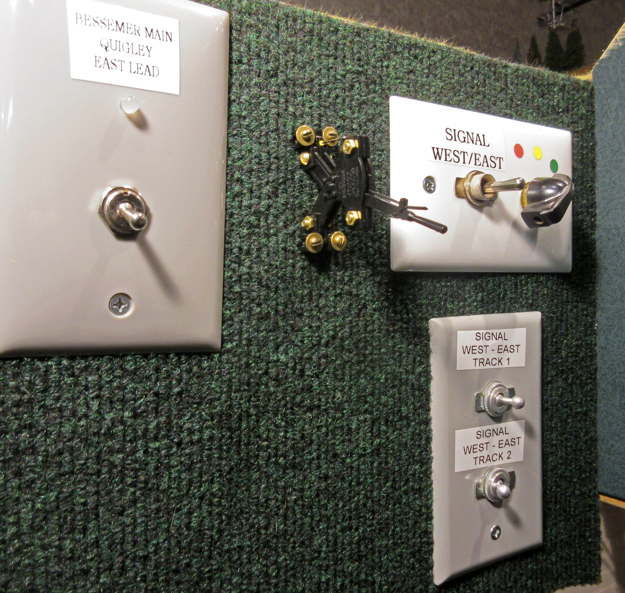
My “manual block” system is not connected at all to the DCC. I control each signal with rotary switches, all powered with an MRC 1400 that used to run part of my former DC layout.
I also use Tomar Industries signals exclusively on my layout. This link is similar to the link provided by Mike, but it will take you right to the signal section of Tomar’s product line.
Well, it IS also about permission. In that there is a railroad specified rulebook which describes the actions permitted and denied when viewing signals.
A dispatcher may modify those rules in a strictly prescribed manner. Thus creating a new, specific and temporary rule.
it’s more than just for show. It allows you to check that turnouts are aligned (trailing point) before proceeding which is something we suffer from while operating on a new layout we’re not that familiar with. And that the block is clear if there’s crowded complicated trackwork.
i thought ABS confirms that permited movements are safe. They might not be because another train is not cleared a block in time or has proceded when it doesn’t have permission.
OK, now I understand what you were getting at. But not everyone above hastheir signals linked to detector or turnouts. Truely modeling any prototype system is difficult as Dave H explained earlier.
Our layouts are simply not big enough for all the aspects to have a purpose, are distances are too short.
Some people extract some features, some choose other features. It depends on your goals, layout size and operational style/interest.
I chose all interlocking/absolute signals w/CTC because I like the busy CTC invironment and I model a double track mainline. Even with what will be a nearly 400’ long mainline run, I don’t have enough distance between interlocking points to justify intermediate blocks or ABS functions.
My typical train is 15’ to 20’ long, my typical mainline block is between 40’ and 60’ long. Typical interlocking sections are 3’ to 6’ long.
Hi, a bit late timewise for a comment but here it goes. Low cost signal control is possible using block occupancy detectors (CT Coils @ $2 ea), signals and an Arduino. Robin Simonds stuff (http://www.thenscaler.com/) has done much on this and is a good basis for going forward - cheaply.
At my club, we have two working signals (so far). Eventually, we will have a real, working system, but right now we just have two temporary signals.
Our situation is that we have one 60’ length of single track that needs to operate trains in both directions (in a gallery with a tunnel). I placed a signal at each end and wired each one to it’s own DCC mobile decoder as we’re a DCC layout (decoders are a Digitrax DH123’s). The mobile decoders are then wired into the track bus.
Both signals are wired to the headlight functions, but in the opposite fashion. So if the west signal’s green indiction is wired to the forward function and red to the rear, the east signal’s green indication is wired to the rear function and the green to the front. Both decoders are programmed to the same address (in our case, the two switch numbers make up the address number: switch 53 and switch 02 = DCC address #5302).
When I’m in the tower, I plug in my throttle, select address 5302 and turn on the headlight function by hitting “0”. Because the signals are wired in opposite directions, one signal will always be red and the opposite one will always be green. It’s not possible for boths signals to be green.
This allows traffic in one direction only through our long single track mainline.
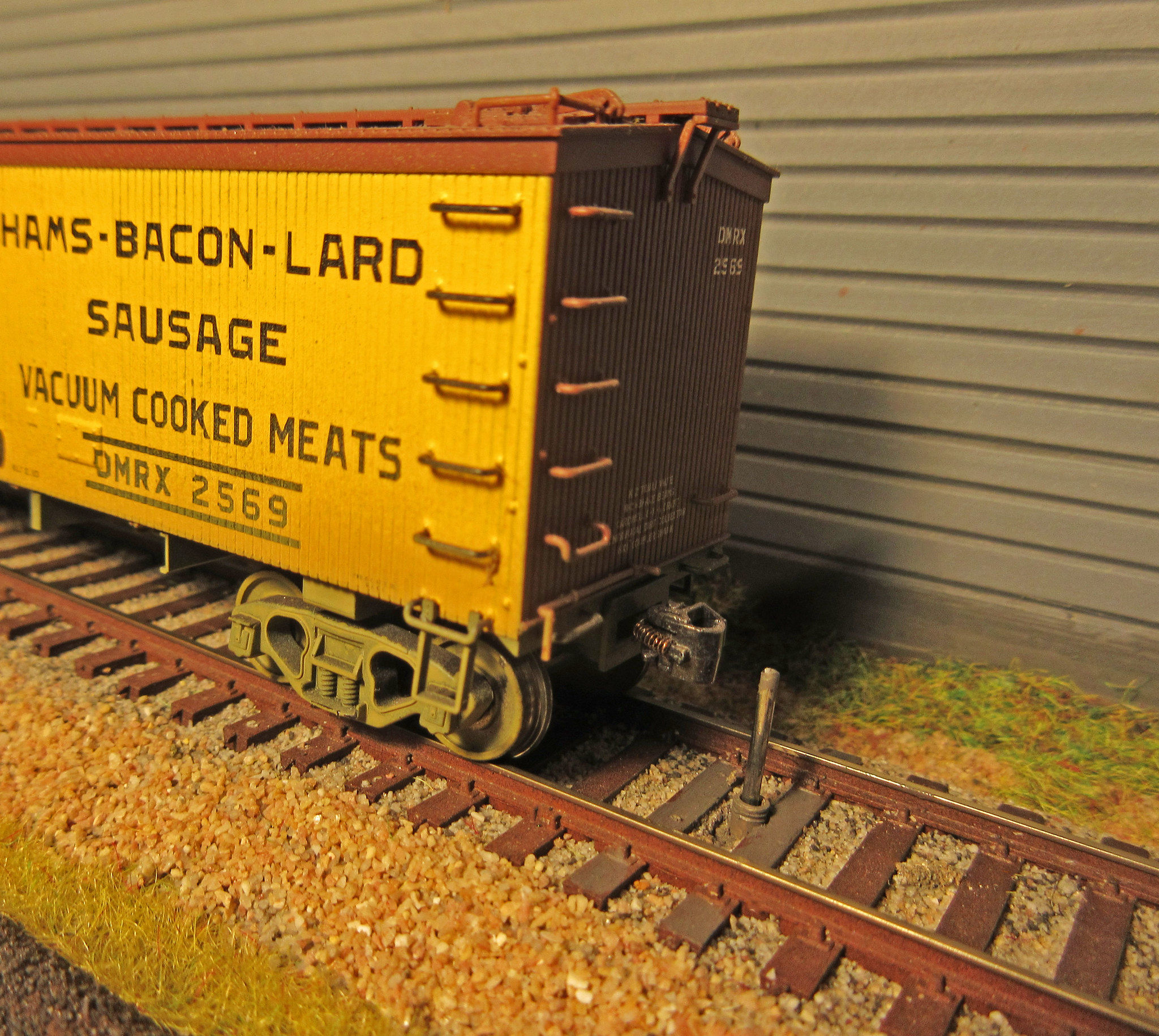 car_stop2 by Edmund, on Flickr
 car_stop1 by Edmund, on Flickr