Signal lights - for show or operations?

I am interested in adding signal lights to my layout. The use of blocks and signals is an area I have not approached yet for my layout but I anticipate jumping into that area in near future. My biggest question at this point is how the signal lights are actually used. I know some people use them as an active part of their operations while other just have a few lights for visual effects and the lights are not actually used by operators to control trains.

I am curious how many of you have a layout that use signal lights as active elements of your operating sessions vs the lights are just there for visual effects?

I really enjoy having signals on my layout. Most are, as you say, just for visual effects, but they do change to red when the engine passes, using mainly IR detectors from Logic-Rail. I decided early on that having a true automatic block system was somewhat futile for my “lone-wolf” operation. Having signals in true prototype locations on the layout would be nearly impossible to see most of the time.

I would have to stop the train until I could run around to see what the signal is, anyway. Still, there are some “absolute” signals that must be obeyed, at a raised drawbridge or a crossing where the roundhouse lead crosses the main.

I have some B&O color position lights:

IMG_5968_fix by Edmund, on Flickr

Some Pennsy position light signals:

IMG_3607_fix by Edmund, on Flickr

IMG_2666 by Edmund, on Flickr

Some manual semaphore train order signals. These are controlled using Humpyard lever controls. In the background you can see some GRS searchlight signals, too.

BnO_5300_full-sm1800 by Edmund, on Flickr

Here are some more GRS searchlights on a cantilever bridge. I really get a kick out of seeing the signal color reflect

Personally, I’m not smart enough to figure out fully functioning signals. I operate a dark railroad. I have operated on and seen layouts using great working signal systems and just assumed they worked by magic! I’ve also seen quite a few layouts with signals that light up but have no control over the trains.

Wish I could help with your situation.

oldline1

My signal system is somewhere between active elements of my operating sessions and just there for visual effects? What I mean by that is that my signals are all wired to turnouts to indicate straight through (green) and divergent (red). So, in that sense, the signals are operational, permitting me to visually check my routes. However, the signals on my layout are not used to indicate block occupancy and are not automated in that fashion.

Rich

on larger layouts, where parts of the layout are not visible to operators, signals are essential for an engineer to know if turnouts are set appropriately by a dispatcher using CTC or if single track is occupied by an on coming train.

Yes, it would have to be relatively large layout such as the Pacific Southern or Tony Koester’s NKP layout.

my understanding is the Koester Layout is deliberately designed so that operators can’t see trains at the next siding and must rely on Time Tables & train orders.

I have used operating signals on all my HO scale layouts.

.

NONE of these signals did what prototype railroads used signals for.

.

I use my signals to indicate polarity and switch position are set correctly for any hidden, or difficult to see, track ahead. This works well for me and prevents accidents.

.

-Kevin

.

After 30+ years of working on club or group layouts, I’m finally starting work on a couple of layouts that are truly my own, where I’ll be calling the shots on all aspects of the layout.

Both layouts are designed for operation. The first one is a switching layout, and the second is the grand “lifetime layout.” In each case, I want to keep things consistent, so if I put a signal somewhere, it will be because it serves a purpose and conveys information.

On the switching layout, the only signals will be at the north end of the industrial line, where it joins a signalled mainline. The switching jobs originate in a staging yard down the mainline leg, so I want to use the signals in a meaningful way, to indicate whether a train coming off of the industrial line can head out into mainline traffic to return to the yard. An old laptop is being set up to control the signals and simulate the flow of mainline traffic.

This is a less-expensive way of simulating the conflicting mainline traffic than actually modeling those other trains and having staging tracks for them at both ends of the bit of mainline. Since only a couple of feet of mainline will be visible, I’d rather simulate its traffic than model it.

The “lifetime layout”, a couple years down the road, still, is being designed to support a number of guest operators running on a stretch of Class One mainline. To make things easier to understand and more fun for anyone coming over to play the “game” I’m designing, any feature on the layout has to serve some kind of purpose and not confuse things. It is important to me that all of the signals will have an easily explained and easily-understood purpose.

You can put me in the “For Show” category. I use single head searchlight three color signals controlled from block detection. On my current layout I started out with a Rob Paisley circuit to operate my eight block mainline. That worked great for over twenty years. When the Arduino caught my eye I replaced the Rob Paisley system with a Mel Arduino MEGA controller. I guess either system could have been used for layout control but because I’m also a Lone Wolf I saw no reason to carry it any further.

To me having an automated layout would take the fun out of model railroading. An occasional screw up keeps things interesting. As I grow older it also helps to keep the brain exercised.

Mel

My Model Railroad

Turnout position for me. I find such signals useful to see at a glance how some turnouts are set, particularly when running at night in a dark room.

There are four general types of prototype signal systems: interlocking, manual block, automatic block and CTC. CTC and interlocking have similar signals and placement , automatic and manual block are different from CTC and interlocking in signals, placement and purpose and similar to each other in signals and purpose, but different in placement.

“Prototype” signals generally have long distances between signals. Most model railroads have a mile or two of main track, most main track signals are 10-20 miles between absolute signals. Prototype signals have specific speed requirements associated with them. A blinking yellow tends to mean 40 mph and a solid yellow tends to mean 30 mph. Model trains rarely have a speedometer.

Model railroaders tend to use signals more for model purposes while trying to display a signal that is reasonable to the situation. Generally green at the top means go, all red means stop and any other combination means slow down.

Dito to what Dave H. says. What signals I have would be manual block. I set the signals manually as to what direction the train is going, and to match the prototype signals I see on the CN mainline, close to my home. My layout is small, no automation.

I guess you could say they are for looks and function.

Mike.

I use signals to control two interlocking areas of the layout. They run when I have operating sessions. Interesting thing about the signals is they’re controlled manually by the dispatcher. I use a rotary switch to change the aspects. In addition, I added a relay to each signal that’s works in conjunction with the crossovers. Let’s say you’re on the mainline track 1 and the dispatcher forgot to set the crossover back to normal from track 2. The signal prior to the crossover will show a stop aspect, even if the dispatcher set the rotary switch to clear. The engineer of the train usually will let the dispatcher know he’s waiting for a clear signal ((very loudly, I might add)also let’s the dispatcher know he forgot to throw the switch back to normal).

This works well for me. I do have a set of signals protecting the north end of the yard controlled by the yardmaster if there’s congestion at the yard.

For now, I am using the old NJ International PRR signals on the main part of the layout and color dwarfs in the yard area. These are the bulb type signals and I run them on 9V DC. As the bulbs blow, I’ll replace them with the new NJ PRR signals. Oh, the relays to control and over ride the signal aspects? Atlas snap relays.

Neal

I am in a group that uses signals for train operation. It is currently the ABS (occupancy detecting) type. There is also interlocking, meaning that switch position is also input into the signal displays.

I am expecting to build a “real” interlocking. It will be a main-line paired crossover.

I have found that, when the signal system is operating, I stop looking ahead for switch position and physical trains, and start looking at the signals. It works better.

Ed

The signals on my layout are definitely for show, but they are also fully functional and (more or less) prototypically accurate. They indicate occupancy and turnout status for the next two blocks.

I used Digitrax components and NJI three-over-three masts and two-light dwarfs. Control via PR-3 to laptop dispatcher panel running JMRI. Can function as ABS or CTC.

Not all signals have been installed. They are N-scale and are very delicate and go in after other landscaping and scenicking is complete in the immediate area. But all signals and the system in general have been tested, and I think things will function (more or less) as planned, with a reasonable amount of Mel’s chaos tossed in just for fun.

Like Dave H: green generally means go, red generally means stop, combos generally mean slow down. More details in my layout thread.

Robert

I also use a somewhat hybrid system. Signals consists of one, two, or there headed searchlight signal Masts. The top head is just for “show”. It is wired to a Rail Logic SA-1 board that utilizes photocells in the track to detect a train passing. Signal turns red, 10 seconds later yellow, 10 seconds later green. It “simulates” block occupancy. If you stop a train just beyond the photocell it will still turn green. The bottom signal of the mast (and middle if noting two turnouts) are wire to the Peco switch motors to indicate turnout position. This is the functional aspect of the system. Everything works well, except the Peco PL13 aux switches, as I have previously posted. Not to hard to figure out if I was able to!

Well, I’m about to start a new layout, and like the last it will have working CTC signaling to control the movement of mainline trains.

It is simplified from actual prototype signals, but provides all the features needed to guide operators and look realistic.

It includes both detection and interlocking features and is controlled by a CTC dispatcher or by local tower operators.

This works because my layout is DC, and the signaling is intergrated into the cab control system.

It also includes working interlockings - that is, turnouts cannot be thrown once a train is inside the interlocking limits.

And, it also includes working ATC - Automatic Train Control - if a train runs a red signal, it simply goes into emergency stop.

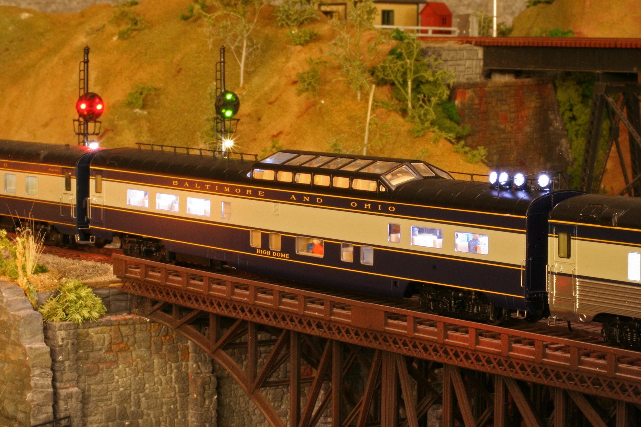
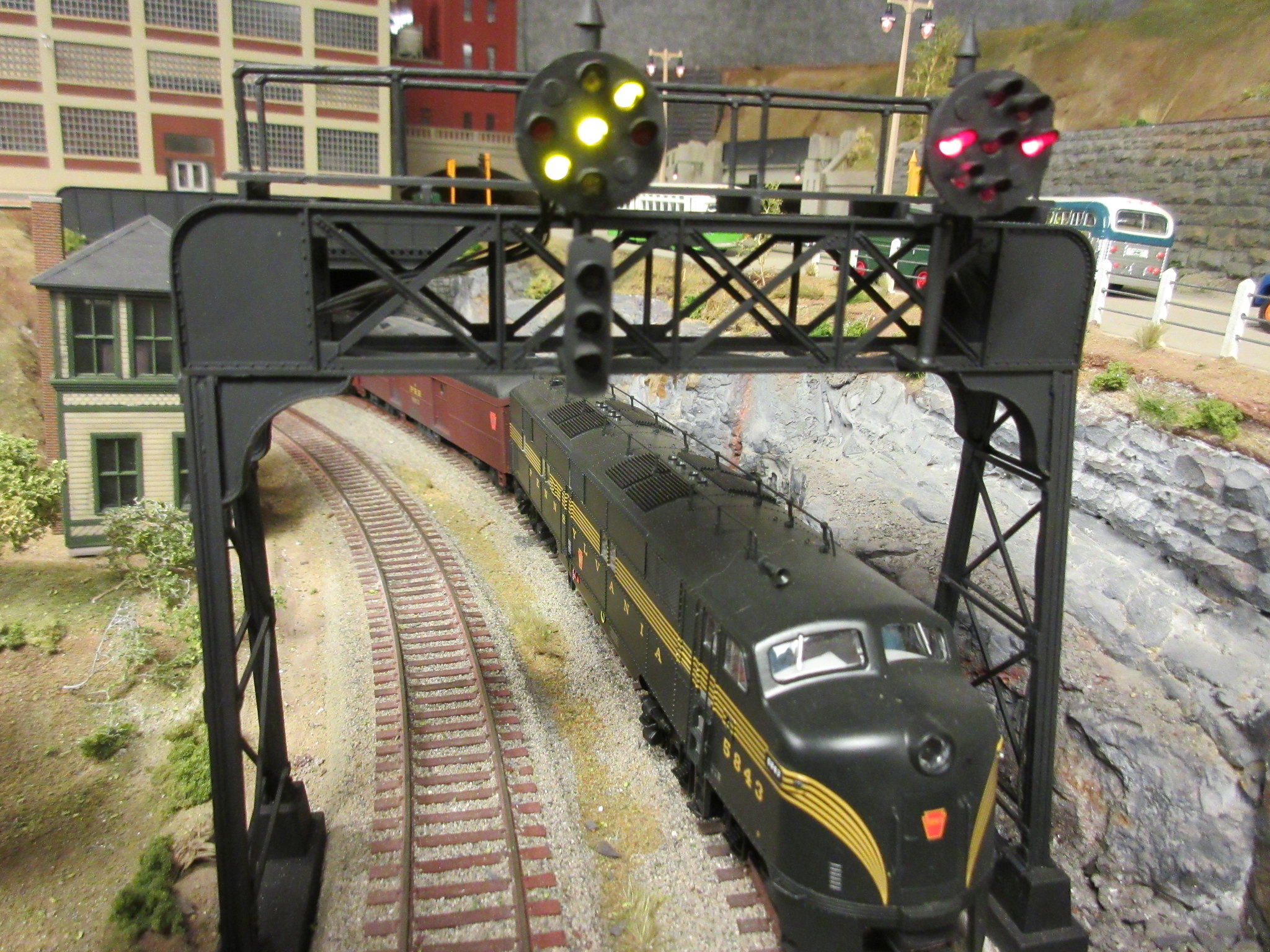
What my system does not have is intermediate block signals, each mainline block goes from one interlocking to the next. No blocks are long enough to justify two trains between any interlocking points. So all signals are interlocking, or absolute, and indicate both occupancy and route.

My trains are long, typically 35 to 50 cars.

My system uses inductive detectors on the block feeders and a high frequency carrier signal to detect stopped trains.

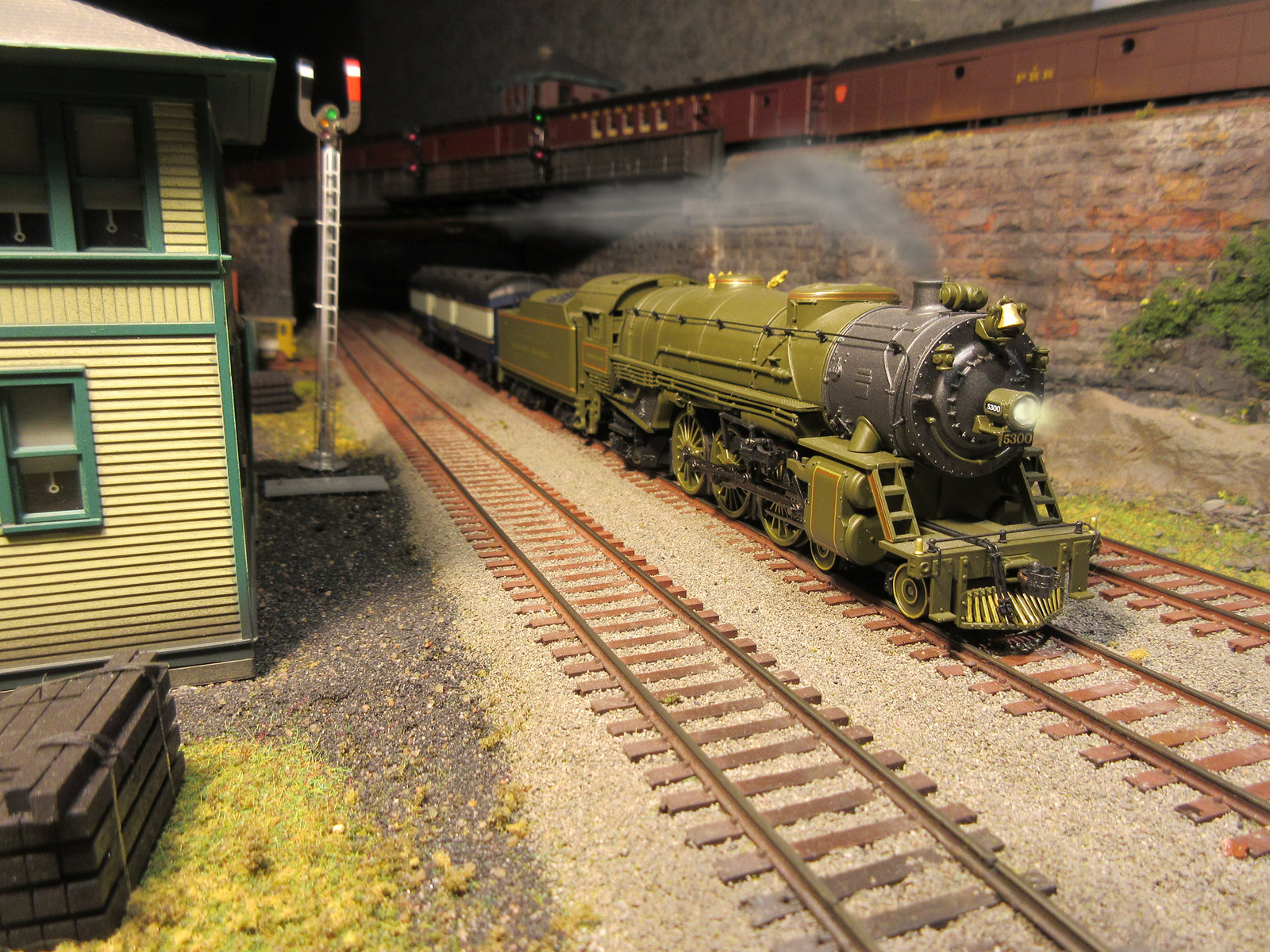
All trains require lighted tail cars, resistance wheel sets are not practical with my detectors and would draw too much power for the size of my trains and the sensitivity of my detectors.

It also uses simple relay logic nearly identical to the logic used by prototype systems years ago.

The CTC panel in simplified, no multi step process. The dispatcher sets the route and assigns the primary block to the desired throttle, the rest happens automaticly.

Tower panels have redundant controls for their interlocking to allow walk around operation without a dispatcher.

Throttles are wireless radio.

There is lots of wire, but actually few parts, a detector for each block, which has built in relay contacts, a 4PDT relay for each turnout, and a

I have a double-track layout in a small space, with a set of crossovers, wired for DC block operation. There are five blocks on each track, with the crossovers and approach tracks as two of the blocks (one for the eastbound track, one for the westbound track.) I have three signal bridges with bi-directional signals; the home signals for the crossovers are two arm, the others are one arm. The signals are US&S TP-5 ‘Rock Island’ type that I found on Shapeways. I purchased signal bridges from Alkem Scale Models and Custom Signal Systems put them together with LEDs.

The blocks are controlled by Dallee Trak-DT detectors. The signals are wired for ABS operation. I used silver conductive paint and 600 ohm resistors to create wheelsets that are detected by this system. This functions like a charm: https://photos.app.goo.gl/z5AC4iX1oMQ2JAye9

The next phase is to build a CTC panel to control the crossovers and entrance/exit tracks from an adjacent yard. The switches and signals will be controlled such that lining a route through the crossovers will set the upper arms to red, and the appropriate lower arm to green, by wiring the signals through the detectors. It’s too complex to explain, and it took me a while to figure it out. Here’s a diagram: https://photos.app.goo.gl/x4bcRzGZyzWaX93S9

The signals, controls, and CTC are my favorite part of this hobby.

My signals are for show. They show where each block begins. I use a DC block system and usually wherever there is a turnout each fork is a new block. I use the old fashion Bachmann non-operational signals. One day I will upgrade them…. But for now they work for me.

Amtrak locomotive #32 leads the Southwest Chief across southern California

That is really cool!

Sometimes signals are for show and sometimes operators actually need to observe them to prevent mishaps. I wish I had taken pictures at the time but my old layout (until about 1995) utilized Dr. Bruce Chubb’s Computer Model Railroad Interface. I placed signals only where operators would be able to see them (maybe 2/3 of the blocks). To give complete protection I attached signal repeaters to each of the walk around throttles. I set up the CMRI code (in PROLOG) to output the next block status to the appropriate throttle repeater and illuminate either the red, green or yellow LED. I bet something like this could be done with DCC and a JMRI interface. Maybe a Bluetooth connection to the repeater.