To indicate when a train is detected a LED is connected to terminals 5 and 6. This LED lights when the train is over the detector. We supply the IRDOT-1 with a 5mm diameter red LED screwed to these terminals. The IRDOT-1 can also operate a seperate LED which lights when no train is detected (green in the diagram). If you wish to indicate no train is present in this way then a resistor (1K) is needed it is screwed into terminals 2 and 3.
Can I use Incandesant light bulbs instead of LED’s ?
Some one gave me some great old Brass Signals. The wiring was shot. I have some 3mm grain of wheat incandesant bulbs I am going to replace the old bulbs and wiring.
The instructions say a relay of up to 100ma can be connected to pins 1 and 2 of the IRDOT-1. This would allow the operation of any sort of light bulbs. Since no information is given on the allowed current limit on the LED connections, and since no resistors are supplied, this would generally mean the limit is something less than 20ma.
Why not replace the bulbs in the signals with LEDs? Then you know it will work. Since you are replacing them anyway. Plus they will never again in your lifetime burn out.
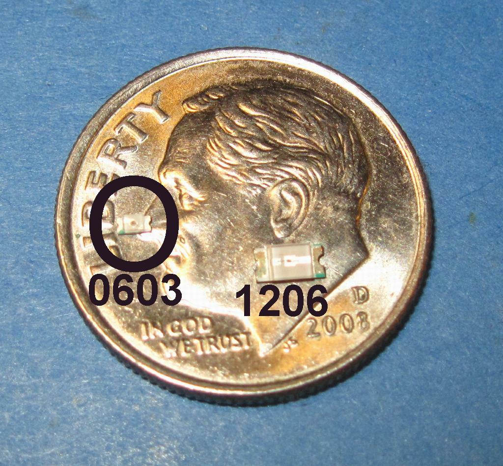
You can get 100 each of prewired 0603 red and green LEDs for $0.99 USD/100 plus $3.00 shipping. That’s a total of $4.98 for 200 LEDs. Is it really worth saving $4.98 to use something that will eventually burn out?
OK, now we have doubled the price if you have to buy the resistors. You are hovering around the $10.00 mark. Not going with the LEDs is penny wise and pound foolish IMHO.
If you need help working with the LEDs we will be glad to assist.
Ok Back to the original question. Is this wiring diagram above going to do what I want?
When the train passes over the detector the light will turn from Green to Red and will turn back to Green when the train clears the detector… It looks that way to me. Am I correct?
To indicate when a train is detected a LED is connected to terminals 5 and 6. This LED lights when the train is over the detector. We supply the IRDOT-1 with a 5mm diameter red LED screwed to these terminals. The IRDOT-1 can also operate a seperate LED which lights when no train is detected (green in the diagram). If you wish to indicate no train is present in this way then a resistor (1K) is needed it is screwed into terminals 2 and 3.
Have you used these bulbs? At a penny apiece I get nervous. The area I need to get into is very small ( Signal Masts ). Is anything except the wire protruding from the bulb.
Yes, after re-reading the ad I’m a little skeptical about that too. I think the pricing may be misleading. I’m guessing that the price is $0.99 for each LED. That is not a bad price, but the minimum quantity is 100 LEDs.
If you are doing signals maybe try these guys instead:
Be aware that the wires on these are rather large and you may not be able to fit them all into a 3/32" dia. (HO scale) mast if you are doing double headed signals. The wires on the first LED listing are much smaller.
There is nothing else attached to the LED except the wires.
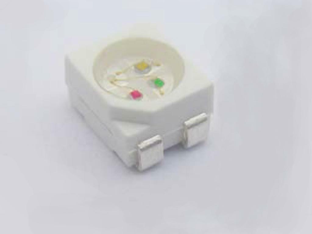
If you solder the wires on yourself you can use magnet wire which will fit inside the masts easily even for triple heads. I can explain how I solder on my own leads. With the right equipment it isn’t that hard. Here are some un-wired RG LEDs:
I don’t see the scale you are working with, you haven’t mentioned scale or size of your signals, only 3mm GOWs. I model HO and a standard 3mm LED is = 10¼” in diameter, perfect for an HO signal. Just wondering why you would using the tiny 0603 LEDs.
I use three color signal heads with a tri-color LED. If you only want two color heads you could go with a 3mm bi-color LED with either two or three pins, series or individual drive.
I am going to be using the IRDOT - 1 with the curcuit described in the first post. I have tested it and it works perfectly and I have several of them.
I did not know the size of the 603 and will be using the 3 mm bulbs. Several of the masts have 2 Seperate heads so I want to use seperate Red and Green Bulbs
What I need to know is how you handle the Anode and Cathode leeds coming from the LED’s with no wires attached? The pictures with wires attatched I have seen have bulkey connections. Are there 3mm LED’s Red & Green with small wires attached? The ones I saw would not fit down the mast.
Also. How are you getting pictures posted on this site. I could probably do a lot better with pics.
i would solder wires to the LED and then with a 1k resistor connected to the the + terminal of 5V, touch one LED wire to the resistor and the other to ground. It will only light when connected properly. Solder the resistor to mark either anode or cathode or tie a know in one of the wires.
see 1st link, “How to Post a Photo on the Forum” on the General Discussions Forum page
I have the circuit made on my bench and it works fine. My question is how do you handle the ancote/ cachode to go into the mast? I assume the two must also be insulated from one another.
A friend of mine is an orthopedic surgeon. He says the definition of an orthopedic surgeon is someone who does an operation, that he has never done before, and the first time he does it, he modifies it.
And doesn’t know he’s modified it.
You have modified this part of the instructions:
Whatever hosting site you use, make sure your settings allow your photo to be viewed by anyone, or all you’ll get is a broken-image icon. The Model Railroader User Gallery won’t work, because it requires you to be logged in. Any site that requires a login won’t work, even if visibility is set to Public. That includes Facebook, Twitter, Instagram, and the like.
I use #36 Litz wire and run both anode and cathode down the mast tube. I don’t like having the brass mast “hot”. I do like Dave’s IC socket idea for mounting!!
I used a built up styrene tubing base for my signals. I slipped several Styrene tubes together to enlarge the signal base to 7/16” so the micro connectors would easily fit through the mounting tube as shown in my earlier post.
If down the road you change the drive circuit to the signals and need to reverse the polarity to the LEDs having both anode and cathode on separate wires is a great help.
Two leads are fine if you only want red/green signals. If you want red/yellow/green signals then a three lead 3 mm LED will work but the yellow indication colour may not very ‘true’. If you want red/yellow/green indications with strong colours then the LEDs that Mel recommended are your best bet:
You don’t really need a diagram. If you have four wires coming from two LEDs and you can’t fit four wires inside the mast, then just solder one of the wires to the top of the mast and solder another wire to the bottom of the mast. That still gives you four connections but only three wires inside the mast.
First, you need to chose a photo hosting site like Imgur and transfer the photos that you want to post to that site. There are several sites that offer free photo hosting but I have found Imgur to be the most reliable.