I am using a skewed plate girder bridge with a timbered deck on my layout. That is, the abutments are not at right angles to the bridge. I am uncertain what the design of the transition from the bridge deck to the balasted right of way looks like. Since the bridge timbers have to continue the full length of both plate girders, how is the “overhang” handled?
Can anyone shed some light on this for me?
Picture of bridge resting roughly where it will go in…
I can’t say for sure, but the decking would not likely extend beyond the ends of the bridge - in other words, it would be cut at an angle to the track. Most “deck” girder bridges were open, with no actual wooden decking, while through girder bridges were either open-decked, or ballasted. Nowadays, ballasted bridges are preferred, as it’s easier to maintain the track elevation and alignment.
The only bridge on my layout which is skewed is a ballasted deck girder, and I didn’t even install guard rails on it - for the “engineer” on a train, it’s hardly noticeable as a bridge. Most of my other bridges are also deck-types, either girder or truss, with many on curves. Since I made all of these bridges removable, I extended both the closely-spaced bridge ties and the guard rails beyond the abutments - not strictly prototypical, but convenient for the situation. I’d suggest that you extend both guard rails at least onto the abutments, if not beyond, though.
Surprisingly, any photos of my bridges showing this detail seem relatively scarce:[swg]
V. S. Roseman had an article on this very subject in this April’s issue of the Journal. He has graphics showing how this is done on the prototype. I purchased this issue because if my current plans for a new layout attain fruition I will need a couple of skewed bridges.
The transverse structural members at both ends would most likely be skewed to reach the opposite girders, with the longitudinal members shortened accordingly. The end transverse members would then be parallel to the abutments, with any decking ending at their outer edges.
The part I’m having the most trouble with is understanding the bridge timbers (ties on the bridge). They must always be perp. to the rail and can’t be cut at the abutment. I also can’t see them being half on the bridge and half on the ground, since their spacing is too close to allow a proper amount of ballast.
The horizontal members are skewed so that they join the side members where they end. Now I have not personaly checked on one but I surmise that they then form a triangle with traditional horizontal members once they can be strung from side to side. Reason for this is so the engineers can place an “off the shelf” designed bridge with a couple of triangular extenisons in position with minimal additional engineering (if it ain’t broke don’t fix it). That would be the most cost effective. Alternately they may already have plans for skewed bridges in their system they would draw upon but I doubt it.
The girders at the bridge ends need to be modified so they end up parallel (at the same angle) as the abutments. Also, cement or stone was more common for abutments for steel bridges as opposed to wood timbers, although wood timbers were often used when a wood trestle abutted the steel bridge.
If you used a ballasted deck, you would use normal ties on the bridge. (“Timber” the bridge floor and add ballast after laying the track.) Then you wouldn’t be concerned with a “half-on-half-off” issue with the heavier bridge ties associated with an open deck.
Both guard rails should extend at least to the maximum abutment length. It wasn’t uncommon (if not the norm) to see the guard rails extended even further.
Would it have been difficult for you to have briefly provided the pertinent information from this article that would have addressed the gentleman’s question? Unless it is a lengthy and complex issue, that would have been more helpful, especially if it is inconsistent with the input provided by others on this thread. I’m interested in the subject but it is often difficult and time-consuming to chase down a particular publication. Thanks.
Why not? Roseman’s article has a number of overhead shots with skewed sides resting on skewed supports and the ties are full length because the ballast runs completely onto the bridge and supports the ties.
I will presume that it is your intention to use bridge track which, I believe, has closer tie spacing than on other track. Whether it is closer or not shouldn’t pose a problem because all you’re going to have to do is run the bridge track onto solid ground and at that point resume with regular track.
The abutment carries 4 end to end steel members, the two main plates, and the stringers/bearing beams directly under the rails, The ties then sit atop the stringers, rails atop the ties.
In a skewed bridge, both ends of all four will assume the same angle as the abutment.
The crossmembers running side to side carry the rail load out to the big plates. Since longer beams sag more than shorter ones, the crossmembers always run perpendicular to the plates, and parallel with the ties.
Since you don’t want the stringers under the rails to tip over sideways, you’d fix them against rotation, box them off at each end, at the same angle as the abutment, generally flush with the landward edge of each abutment, with material similar in cross section to the cross members.
Clearly, your ballast won’t stay between ties over empty space. The last bay between ties, that’s over the concrete abutment is the last tie bay that will hold gravel. However, your ties are at an angle to the abutment, so the gravel line, as seen from above, will assume a stairstepped angle pattern. In short, the last ballast will rest on the riverward edge of the abutment.
After the steel and ties are in, you sprinkle, and the same laws of gravity that govern the lay of ballast on the prototype will govern your layout, right down to the overspill down on the river bank, if, of cou
Do what the prototype railroads prefer to do. Lay a solid deck on top of the bridge girders. This deck will hold the ballast. Use regular ties and ballast on the bridge. (I know I already said that but I’m not sure everyone was listening.)
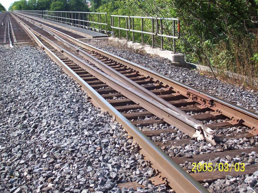
Actually, the OP’s use of the word “decking” is confusing the issue: as I read it now, he’s referring to the ties on the bridge. As others have mentioned, if the bridge has a “floor”, then the entire bridge will be ballasted, and the ties will be spaced as with regular track. If the bridge has an open deck (steel framing only), then the ties will be spaced closer together - it would make sense if the closely spaced ties extended along the track beyond the outer edges of the skewed abutments. As also mentioned, ballast would be placed between the ties, regardless of the tie spacing, anywhere that there was something beneath the ties upon which it could rest. When viewed from above, all of the ties, both on and beyond both ends of the bridge, would be at right angles to the rail, and the end of the ballast would follow a line parallel to the skewed abutments. As you can see in the photo below, even though the bridge is not skewed, the bridge ties extend beyond the bridge onto the top of the abutment, and are ballasted the same as the regular ties. Also visible are the guard rails, which extend well beyond the abutments.
The guardrails were there to reduce the effects and possibility of a derailed but moving car hitting the bridge structure or pulling the train into the abyss. They were sometimes seen in tunnels for similar reasons. On a curve, sometimes only the inner rail would have a guard rail.
The ‘rails between the rails’ are bridge guard rails, and they are spaced far enough from the running rails that a derailed wheel will drop down between them and ride either on the ties or on the base of the guard rail. That holds the derailed truck in line, so the derailed car will (hopefully) remain coupled and not get over far enough to damage the bridge structure.
They are frequently smaller than the running rails, always taper together as shown and sometimes are joined at the ends with special, made-for-the-purpose castings similar to frog castings without the guard rails.
. . . . . . . . . . Now that we have all manifested our Rocket Scientist mentality for Tuesday, the 17th day of June in the year of our Lord Two Thousand and Eight . . . . . . . . . .