The signal changes as a train passes on the right hand track within 5 minutes.


And what is this thing.

The signal changes as a train passes on the right hand track within 5 minutes.
And what is this thing.
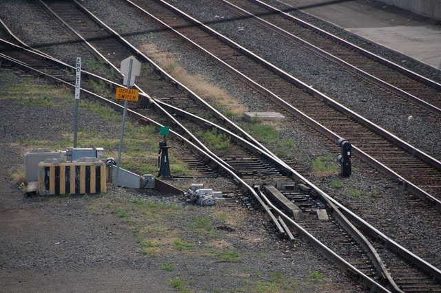
can’t tell ya much about the signals but I do know that the bottom picture is a piece of Derail equipment thats used on most sidings and in some yards. All are used as safety measures to varried degree. They usually have a sign near by marked Derail or have a D indicating a derail location.
That is a derail. Usually used on a siding or spur to prevent rolling stock from rolling back out onto the mainline incase the crew forgot to set the car’s brakes. Notice in the photo that the siding is lower than the mainline. Do you recall if the siding was on a grade? Was this on the downgrade end of the siding?
Chip,
(Borrowing your photos to explain)
Train within the interlocking plant. Signal is set to STOP.
Train clears the interlocking but is still in the next block. Signal changes to Restricting (Proceed prepared to stop with in one half the range of vision short of a train, derail, misalinged switch)
Train clears first block after interlocking, but occupies the second. Signal switches to Approach (Proceed prepared to stop at next signal not exceeding medium speed)
Train clears the second block beyond the interlocking. Signal upgrades to Clear (Proceed at Normal Speed)
Nick
Looks to me like a true scale Caboose Hobbies ground throw that moves a derail over to, and away from, the closest rail. [:)]
I haven’t a clue about the signals, but I wouldn’t mind being edumacated.
The first picture (as the rear of the train passes the signal) shows the signal has dropped which indicates a train is in that block. The signal will drop when the train gets about half an engine length past it.
The second picture shows the signal is giving the next train a “Restricting” signal which means if a train showed up at that moment and saw that signal they would have to "Proceed at restricted speed (travel at no more than 15 mph but you must be able to stop within HALF the distance you can see) so the train would travel VERY SLOW, by looking at the pictures, if I were the engineer I would not be moving more than 4-5 mph because you can not see around the corner.
The Third picture shows an “Approach” signal, which means “Proceed prepared to stop at the next signal and you must not exceed medium speed (30mph)”. So traditionally the train you saw pass is now a whole block ahead now.
Then the fourth pic is a “Clear” signal.
Now what is interesting is that you said it went through these in about 5 minutes and in the second picture you see a tractor trailor sitting in the curve (possible in another siding). So either that intermodal train with the Roadway Express semi is hauling BUTT and the blocks are small or the signal is being physically changed by the dispatcher.
Absolute stop and stay right hand track.
Bottom signal is a Pennsy “Take Siding” model if all are lit you are to cross next switch off the track you are on. This case it’s off.
Next picture, Yellow restricting, slow with ability to stop before next train or red signal.
Next picture
Slow to medium speed. THe rule book of railroad will specify it. Expect next signal to be either stop and stay or restricting
last picture
Signal up and down means proceed at up to max track speed.
All signals appear to be on the Pennsy model which means all indications except red are going to be yellow.
The signal on the left side govens the left track. Apparently there has been some changes between Transition Era and Modern Era signalling.
Just to give a sense of distance, the signals are a good 300 yards from me. The train is upwards of half a mile. I just have it on max zoom.
The tractor-trailor is the rear of the train that just passed.
nbrodar has it bang on as far as the signals go, the other device is an automatic derail, either controled in conjunction with the signal system or activated by the keypad of an approching locomotive.
The derail is not automatically controlled. It is hand thrown by a crew member. The device you see connected to it contains electrical switches for activating signals.
Here is a picture of a different method of Derail. This was taken at the South end of the Kamloops Yard on the CP mainline in Kamloops, British Columbia. The tracks to the right are the mains and the track with the derail protected the main from the yard.
The Derail is automatically controlled, but the switch directly beyond obviously isn’t.
You’re right, after looking at it again I can see that it is a manually operated derail. We have automatic derails on the OCRR and the type of derail used in the photo is the same as used on the automatic ones. Sorry if I misled anyone.
The “thing” is a derail as stated. The “thingS” closer to the camera are modern Insulated Block Joints (IBJs in UK language).
An IBJ is always normally a straight acrosss the track pair of joints (So this one is staggered a couple of feet just to prove me wrong [banghead]). As the name says, they are insulated electrically. Ordinary rail joints don’t have to match up for position and are not insulated. If there is a track circuit (or there was one) an ordinary joint will have an electrical bond round it to ensure continuity for the electric current without relying on the joint… which can shift around with expansion and contraction due to heat/cold and the movement of trains.
An IBJ insulates a track circuited length of track from another track circuited length of track OR an non-track circuited length of track.
A Track Circuit is a known amount of electricity put into one rail that passes along that rail to the IBJ, crosses over to the other rail and is detected by the equipment. All the time it does this to the setting it shows the line “Clear”. If the rail is broken, the circuit fails or anything bridges electrically between the rails then the track circuit shows “Occupied”. Where this is linked to the signals it may (usually does) set them to red.
Notice that the TC fails to red. This doesn’t work if something jumps the rails and stops making contact with the circuit… which is why FREDs are still necessary to show that you haven’t left anything behind. Also a derail on another track - maybe endangering the circuited line - or a tree dropping across the line won’t show.
The track circuits will most time
Am I wrong as a kid we used to see these on tracks, they could be flipped over at will, hopefully today there are locks on them to prevent the little angels from derailing trains.
If you look you can see the lock across the throw bar. I didn’t think about it until you mentioned it and I went back to the original photo to look.

There’s one on the turnout leading to this siding as well. That’s my kid and my vehicle. We are pretty much out in the sticks so the trains are approaching ramming speed.


In addition to the locks, any switch or derail in signalled territory is also interlocked with the signalling system. In Chip’s pictures, the big box behind the operating handle is the mechanical interlock and the silver box on the ground connects it to the signal system. Once the handle is moved out the normal position, the signals governing the use of that block should all drop to their most restrictive aspect.
In dark territory, through, the lock is all the protection you have. Which is why most RR locks tend to be substantial pieces of metal, with really wierd looking keys.
Nick
It looks to me like you have two different set-ups here.
The derail. This looks like the throwbar is locked by the padlock; which is retained by the chain (I think). There is a semi-circular device which appears to “hold down” the throw bar at each end. BUT it doesn’t extend into a keep and, in fact, barely goes half way across the bar. I suspect that this is electrical detection that “proves” the throw bar in one position or the other. It may be that the back end of the bar that rotates across is secured by the padlock. [All a question of where exactly the pdlock fits into the lock mechanism]. The semi cicular thing sticking up will contain the two position switch that sends the signal to the interlocking/ctc to indicate what position (or no position) the throw bar is in- if I’m right about detection.
the switch control. Again the switch is thrown by the throw bar and, if I’m correct, it is detected. You also have another lump of machinery. this has some armoured cable conduit going to it. I suspect that this is a point/switch lock (similar to one of our Facing Point Locks) that is remotely controlled and holds the switch blades in place very securely. It may hold it in the Normal position only or either Normal or Reverse. [There are two bits of conduit, one to the metal box Nick mentions and another one curving down into the ballast which can be seen beyond and below the throw bar. incidentally the throw bar still has its own padlock].
A switch lock of this kind doesn’t need the power of a point motor to operate. All it does is push a lock into or out of the slot in the connecting bars of the points (between the throw mechanism and the blades. It will either make or not. Once in place it doesn’t do anything. Like the throwbar its position will be detected/proved and send an indication back to the controlling system… which may or may not give r
Chip, I pilfered your pics and labeled the various parts…
Here is the switch and associated gear. In addition to the mechanical T&E lock, this switch looks to have an electric lock, that is released by the dispatcher. After the DS release the lock, some sort of indicator light will show in the top the machine, and the crew will be able to remove the T&E lock and operate the switch.

Here’s the derail and associated gear. When the cars are behind the insulated joint and the derail are switch are restored, the track circuit will clear.

To add to some comments Dave made. Most dedicated MoW equipment will trip the track circuits. Some small MoW equipment, and most Hi-Rail vehicles won’t. For the most part, all MoW equipment and Hi-Rails will operate under a track warrant, regardless of whether they trip the track circuit, or not.
Nick
One more thing. The dispatcher most likely “fleeted” the signal, so that trains traveling in the same direction automatically receive signals to proceed.
Nick
About 50 feet from the turnout in the direction I did not photograph, is three large electrical boxes–no doubt the circutry for the block(s).
Edit: I scanned through the photos I had taken and yu can see both the switch (center) and the power boxes to the right.
