I am currently working on a kitbash of a Roundhouse 4-6-0 to try and make it look something like Grand Trunk’s #320. Sorry but I can’t find the one picture that I have of #320 on the internet. (If somebody can come up with more information on Grand Trunk #320 then I will give you three smilie bows in my response. How’s that for motivation!?![(-D]).
My specific question is: does anyone have any pictures of the interior of a steam engine in the early 20th century. I want to know where to mount the controls, and I would also like to know what the seats looked like, although the seats are a minor issue. I have tried the search engine here and I have googled the topic but nothing came up.
Dare I use the standard greeting of out fellow modelers in the southern hemisphere![:D]
The pictures are absolutely fantastic. Some of the controls that I have are very similar to those in your pictures but others not so. If I knew what the controls were called and what they did I think I could do a much better job of identifying where they should be placed.
Here are the two control mechanisms that I have:
I have a general idea of where these controls should go but I don’t want to fudge it so your advise is very much appreciated.
Gidday Dave, don’t mind how you greet me though I don’t necessarily respond that well to “Hey You”. [swg]
The item on the left is an air brake stand with its associated plumbing, I’m not at all sure about the item on the right, is it a type of throttle??? If so I would suggest that it would be wrong for your 1920s Baldwin. Hope someone more knowledgeable will either confirm or deny.
Have dug up a couple of videos that may help or confuse. [*-)]
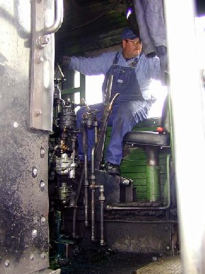
I am making the assumption that the loco in the next video is a 1916 Baldwin built 2-8-2 that"s operated by the Chehalis Centralia Railroad. The throttle is again mounted on the backhead, with the Reversing Lever,or Johnson Bar on the floor behind the delightful Engineer, who is also using locomotive brake.
The item on the left is the throttle. It would be hooked up with linkage to the starter valve on the steam dome. The handle would be hanging down on the right side of the cab. The curved ratcheting lock would be just to the side of the firebox as high in the cab as possible. This item should not be confused with the reverser. The reverser would be mounted to the floor of the cab. Your time frame would be a latching type handle about 3 feet high from the floor on the right side of the cab. This is where the term “Down in the corner”. This means the engineer has full amount of steam admitted to the cylinders. Later when power reverser were coming into fame the reverser turned into a wheel with a handle.
If you go to google books you can either view or download a book titled Locomotive Cyclopedia. Tons of info right from the builders and railroads in them. That is one thing about the early railroad men. They shared everything.
Thanks for confirming my suspicions. (By the way, I think you meant to say that the item on the ‘right’ is the throttle, not the left, which I am sure is a brake stand thanks to JaBear). I will have to come up with a reverse lever. Thanks for the description.
I am not a rivet counter so whether or not they are accurate for the specific locomotive is not too much of an issue. I’m fine if they represent the theme as it were (with apologies to those who are offended my my lack of accuracy).
I apologize. I did mean the right. The locomotive cyclopedias are terrific resources for many a project. Download as many as you can. If my memory serves me correctly they were printed every 3 years from 1889 on up. Most are mainly filled with component manufactures adds and rail road master mechanic drawings for the newest locomotives at the time of printing. These books really show what it takes to build a locomotive.


