Why are there differences in steam locomotive throttles? IE why are some mounted on the roof and have a vertical appearance vs those mounted on the rear of the firebox that have a more horizontal appearance?
I’ve been searching the internet and can’t really come up with an answer.
As the purpose of the throttle/ regulator by opening or closing the valve in the steam dome thus controlling the supply of steam to the cylinders, seen here in this animation at .56… https://www.youtube.com/watch?v=d1OpJzWTk8g
… I would suggest that whether the throttle/regulator was in the vertical or horizontal plane was up to the individual locomotive builder’s design, depending on the location of the steam dome, the routing and complexity of the throttle linkage, and the mechanical advantage required to manually move the valve in the steam dome.
Whereas there are power assisted reversing levers, or Johnson Bars, I have been unable to ascertain if any throttles were.
Here are a couple of links to videos you may find interesting… https://www.youtube.com/watch?v=Llj0nsQmZdY
The horizontal throttles are connected to the throttle valve by a rod that goes inside the boiler to the steam dome where the valve is located. The vertical levers are connected to a “front-end throttle” valve that is located at the forward end of the boiler by external linkage.
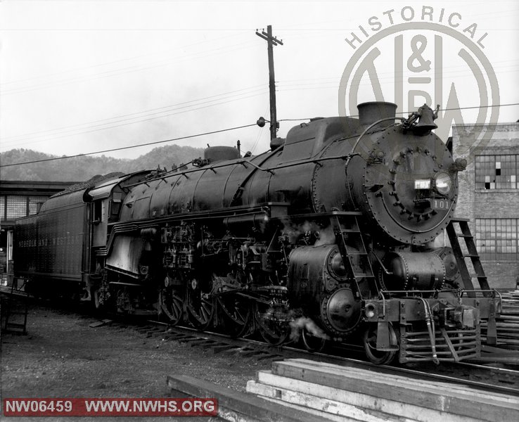
Actually, the K1 in the photo has a throttle rod that runs outside the boiler, in common with front end throttles. I think a (near) horizontal throttle handle generally connected to a throttle rod that entered the backhead and ran inside the boiler. But I’m on shaky ground here & will defer to anybody who can give more reliable info.
Be careful – you’re getting ‘salty’ with where the throttle valve is before you should.
Modern American locomotives don’t have the throttle in the steam dome; they have what is called a ‘front-end throttle’, which is a cam-operated arrangement of poppet valves at the other end of the dry pipe from the dome. This is most easily actuated by linkage external to the boiler shell (although it could be run under the lagging/cleading on the outside of the boiler shell).
As a peripheral note: many larger locomotives have an intermediate lever in the throttle linkage that reverses the direction of actuation for half the linkage run. This is to neutralize the effect of differential expansion between the boiler structure (to which the cab attaches for support) and the linkage itself.
There are some locomotives that have both a dome throttle and a front-end throttle (one of them I believe is the Russian P36 class 4-8-4). I do not know how this arrangement is controlled (other than that it would be unwise to work both throttles with a common linkage) but would certainly like to find out.
There were air-assisted throttles; the ThrottleMaster advertised in '40s editions of railroad trade magazines was an example. The infamous PRR T1 used a Franklin Precision air throttle, for which drawings still exist.
Another thing to note is that if an engine has a front end throttle it is therefore super heated. The reason to have a front end throttle is the steam still comes from the steam dome and is fed through the super heaters then the valve is after. With the super heated steam preheated it gives the locomotive a faster start with more energetic dryer steam. And for the sake of explaining for those that may not know, super heating steam is useful because it basically ups the pressuse of the steam making it more energetic with out putting more strain on the boiler itself. Free higher energy raises efficiency, or at least more power for no extra fuel cost.
One of the things we historians of the steam locomotive have to consider is the fact that we have the advantage of looking back over some one hundred-fifty years of locomotive development.
That word development is crucial in our discussions of the steam locomotive because at any given point in time there was a broad range of locomotive designs from different builders in use and the ages of the locomotives varied greatly since some fifty year old, hand fired, non-superheated engines could be working right along side the latest “superpower” from Lima or Baldwin.
The variety of locomotives depended largely on what the needs of the particular railroad were and the preferences of the Superintendant of Motive Power and Chief Mechanical Officer were. If it weren’t for the likes of Paul W. Keefer or J. T. Wallace we may never have seen the New York Central Hudson or the Pennsy K4.
In just the sheer numbers of locomotives (the Pennsy had 7,556 on the roster in 1924; 4,848 in '46!) there is going to be quite a bit of room for variation.
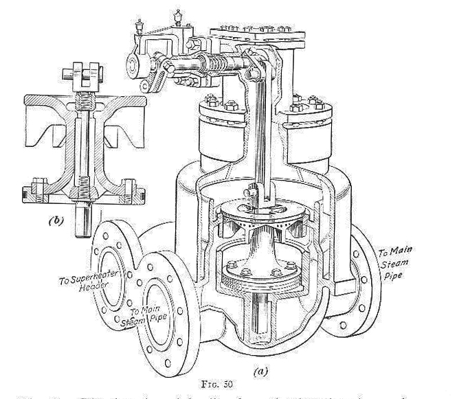
Here’s a sketch of the front-end throttle linkage that Wizlish refered to:
The railroads learned of the advantages of superheated steam in the early 1900’s. There were applications in Germany in 1898 and England in 1906. Tractive effort and economy were two major factors in the adoption of the superheater but increased maintenance costs had to be considered, too. One of the factors for the need to adopt a front end throttle was the fact that as the boiler diameter increased there was less headroom for a steam dome throttle.
Just to toss another shotgun shell on the fire, modern Japanese locomotives had dome throttles with outside linkages. They also had superheaters. I don’t know what arrangements were used to keep the superheater loops from overheating.
The Russian Decapod also had a dome throttle with outside linkage - but no compensating link. I wonder what was done to prevent throttle creep.
Interesting. And yet there was lotsa superheating before the front end throttles were adopted. One possibility is that the potentially overheated superheater tubes were surrounded by tubes that were cooled by boiler water. And that the heat radiated by the superheater tubes (sucked up from the flue gases) was absorbed by same. Don’t laugh–it could/does happen.
Nothing, apparently. It does argue for making sure the reverse gear is in the zero position. During operation, of course, our highly trained operator adjusts things accordingly. As, of course, we operators still do. Accordingly.
Yes, the superheater flues were surrounded by boiler water but that didn’t help cool the superheater tubes within those flues. There were front end dampers of various designs that would bypass the hot gases when the engine was drifting, throttle shut. Sometimes you could see a counterweighted lever on the smokebox near the front flue sheet.
The engine I’m familiar with, a 1918 USRA ALCo Light Mikado had a Superheater Company Type A arrangement with an internal damper and a double-lapped dome throttle with internal linkage.
Many different designs were out there so it is tough to generalize on one design. You have to look at each particular locomotive and with each locomotive, when—since over the lifespan of some engines many appliances were changed or removed alltogether.