I have a Lionel 4-6-2 steam locomotive tender that has operated just fine until I recently put it on the track. The whistle is now stuck on and continues to blow whenever there is current applied to the track. I’ve used different power sources and have tried other engines on the same track and they all work just fine. I’m guessing something is stuck or defective on the control board.
I would appreciate any suggestions on what might be the cause. I can provide further details if I know what information would help.
As always, thanks for the help.
Mickey
o Model number
o Age
o Whether it has a whistle relay and air whistle, or electronics and a loudspeaker
Bob,
Lionel 6-18639, Reading 4-6-2 Steam Locomotive & Tender. Engine number 639. There’s a number on the maintenance instructions: 71-8639-250. Instructions have a 1995 date. I bought the engine used but I believe it’s manufactured about 1995.
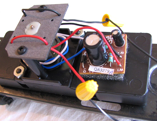
It has an air whistle and small circuit board with these numbers: QA3279A.
Here’s what it looks like.
I appreciate your help,
Mickey
Reverse the wires at the transformer.
Jon [8D]
Thanks Jon,
I just tried that and it still keep on whistling. I also tried a different transformer with just wire leads on the workbench and still the same thing.
Still baffled,
Mickey
I used to have a G Scale loco that did that. It had a different setup though. The whistle was an air whistle on a timer. After a prescribed amount of time passed a small magnetic plunger pulled down the end of a plastic tab that was mounted on a pivot at the midpoint. The other end of the tab lifted exposing the hole for the whistle and closing a circuit that activated the motor for the whistle. It would remain activated for two or three seconds then disengage until the cycle repeated. Something went wrong with the electrical switch that activated the motor and the whistle started running all the time, making the whistle when the tab was up and making a kind of weird hum when the tab was down. I ended up disconnecting the motor.
Yours looks like it employs an electronic switch. I’m don’t know much about that type but I’d wager to say the problem is on the circuit board. Your only option may be to replace the board.
Call Jeff at the train tender and see what he thinks he probably tell you what to do and I bet it has something to do with replacing the electronic board. 585-229-2050
The board is definitely bad. #610-8633-010 (alternate #610-8633-020) is the part number for the board.
Brasseur has the -020 part.
Larry
OK, thanks. I’m wondering if anyone knows what part on that board is faulty and if it could be replaced. Maybe it’s just better to replace the whole board. And, if that’s what I do, I’m wondering if there is another board with better features that I could use in it’s place.
Thanks all,
Mickey
Your picture doesn’t show the parts that likely are bad. Somewhere on the board there must be a power transistor or electronic switch that turns on the motor. In order to check transistors and diodes you need a meter and you need to know how to check simple semiconductors. Diodes are very simple. Transistors are a little more complex, but still simple. Integrated circuits normally cannot be easily checked with a meter.
Give us some better pictures and it is possible we could walk you through finding the bad part.
My experience with this stuff is that often the circuit designer will use a transistor that is too small, and the high current density at the junction will turn the transistor into a short circuit.
If you can, take the circuit board off of the sticky pad that holds it and give us a picture of the back side. This circuit looks pretty simple, so there is a chance it can be fixed. You will need to know how to solder and have a low wattage soldering iron, maybe about 25 watts.
The QA sticker is likely the sticker of the quality assurance tester that tested the board.
I would say the darlington amplifer is bad. If I remember correctly the PN for the NPN darlington is MPSA13. I just replace the boards now. If you need a board I have them.
Bill
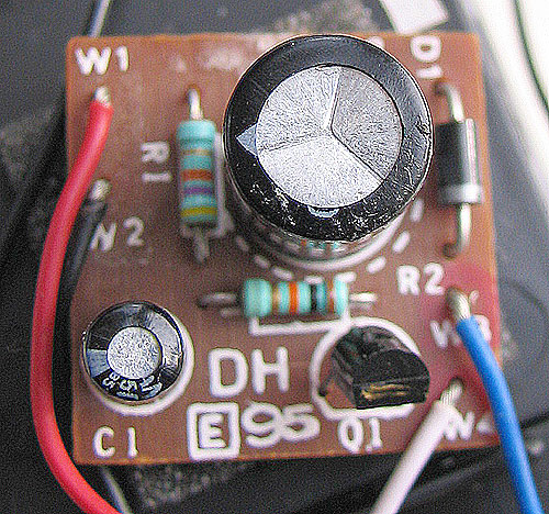
A top-down view of the board is here.
Larry
Maybe that little one at Q1 is sufficient for the motor? Are there any parts on the other side?
It would help to see the other side of the circuit card. But it all looks so simple that I will go out on a limb and say that the diode and the larger capacitor are the DC power supply. The 7500-ohm resistor and the smaller capacitor low-pass filter the track voltage to get the DC component that commands the whistle to blow. The 10-kilohm resistor drives the base of what has been identified as a 500-milliampere Darlington transistor to apply the DC supply to the whistle motor.
The Darlington looks like the only possible component whose failure could make the whistle blow continuously. Transistors typically fail shorted. I’ll bet that the assembly can be repaired simply by replacing it.
I can solder this sort of thing as long as I find out what to do. I don’t know much about circuit boards and their components but would like to learn. Here are a few more images of the back of the board and the top as well.
As I stated I don’t know what each of the components is or does but would be willing to try fixing it once I knew what to do. I really appreciate everyone’s input. A new board is only $7 and I don’t know what the component I need to replace would cost or where to get it. We have several electronics places here in town along with Radio Shack.
Thanks again,
Mickey
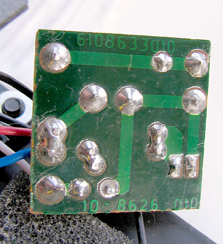
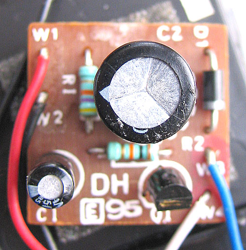
Well, the top suspect is clearly Q1, it’s the only thing on the board that appears to offer the switching capability. What are the numbers on that part?
It looks like I got it right. I notice that the card marked “98” has a 7500-ohm resistor, while the “95” card has 4700.
You can get the MPSA13 Darlington transistor (Q1) from Mouser (their part number 512-MPSA13) for 16 cents, plus $4.95 shipping by USPS. I would order several if I were you.
Replacing Q1 should be easy. Just cut off the bad transistor, unsolder the leads one by one, and solder in a good one with the same orientation.
Is this something that will probably happen again? Our grand kids are the ones who run the trains mostly and they like the whistle. So with more use is this going to happen again so I should get a number of these just in case? From what you’re saying I have the “95” card. Can I upgrade it to the “98” card so that this is less likely to re-occur? If so, how would I do that and/or is it worth it?
Following your instructions I shouldn’t have a problem doing this. Is the MPSA13 Darlington transistor a common item that I might find at a local electronics supplier?
Thanks to all of you for your help.
Mickey