I’ve been busy over the past week or so, building a couple of switch panels to operate the turnout motors using toggle switches instead of the DCC handheld.
The idea came from my exhibition operators who are somewhat traditional and relate easier to the traditional method of turnout operation rather than punching numbers into the NCE handheld controller - especially in an emergency.
Luckily the accessory decoders I use - NCE Snap-It - support seperate switches, and allow this option in addition to the DCC method.
Therefore, I can operate the turnouts using the accessory button or Macros on the DCC handheld, or flick a toggle switch on the panel.
I have made 2 panels - one for the East yard and one for the West.
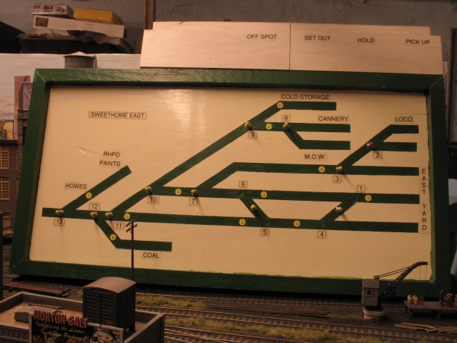
East Yard
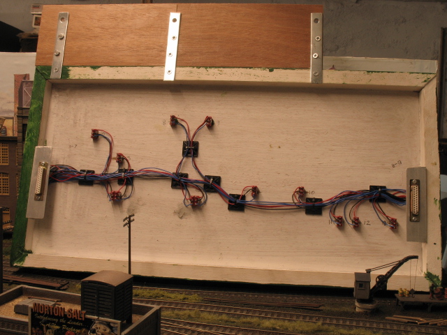
Rear
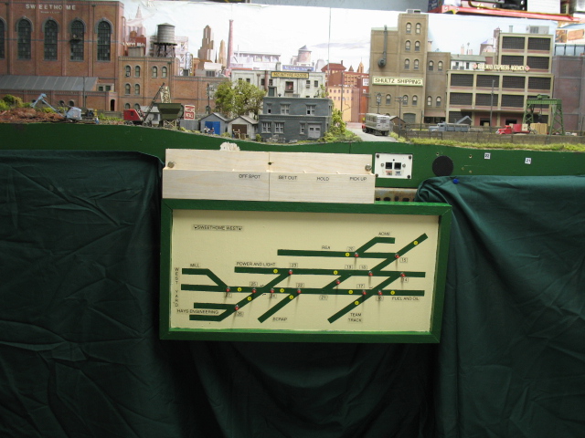
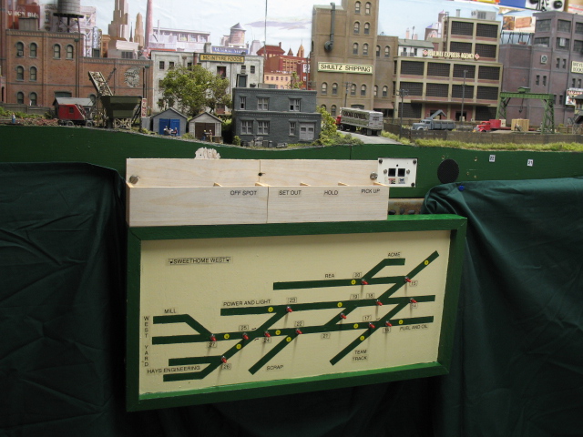
West Yard
I have included the DCC address for each turnout on the schematic, as well as the uncoupler locations and the car-card industry locations to assist newer operators.
So far, I have managed to wire up the boards so that turnouts 14-22 are fully operational. It’s a slow ‘one wire at a time’ process but not too complicated.
Would you care to share your technique with us? A local modeler used an interesting method, painting one side of plexiglass yellow, then masking and spraying the otherside black, resulting in very professional panels. However, I cannot imagine the pain of drilling plexiglass. Your panels look great and a lot easier to build. For that reason I’m very interested in what you have done here. What material did you use for the board? Any recommendations?
Clear, easy to understand and very professional looking. Well done.
My own track diagrams look very much like yours, but are done with Dymo tape in various colors. Base is some yellow styrene plastic salvaged from obsolete (Kodak film) display units intercepted on their way to the dumpster - it drills nicely and is stiff enough to tolerate the stresses associated with heavy-duty toggle switches.
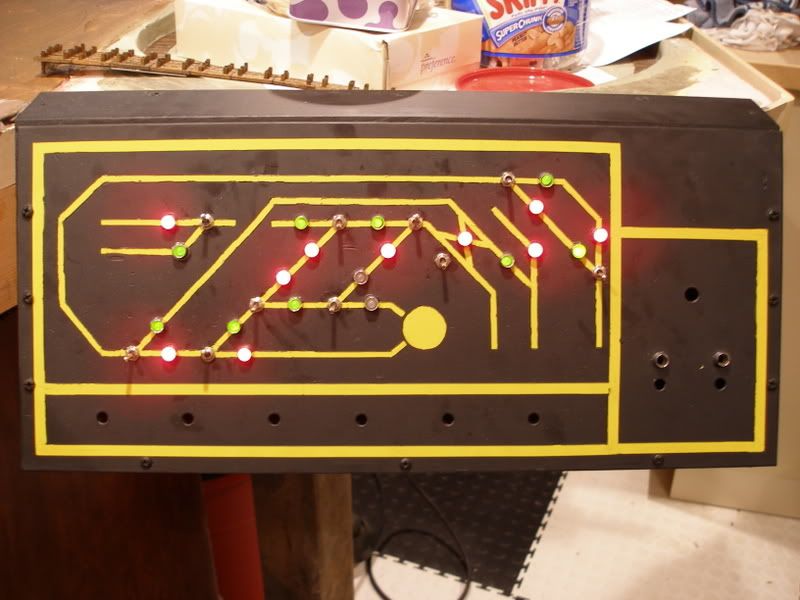
I used a 1/16 steel sheet and drilled through all the holes… my wiring is done by pluggin 6 pin (RJ22) wires into a breadboard I have wired for going to the appropriate places. I use this method, because I have dual site control of my turnouts. By this, I mean I control them from the control panel, or walking around at the turnout. (See this diagram)
LED’s are at both locations. Yeah, the wiring is a pain, but is fun to do it either way. Oh and yes, I know that one is NOT lit in the middle…this is for a future turnout I have yet to place. Also, the empty holes on the bottom are expansion for accesories and on the right for my turntable (someday, when I get to it!)…
I routed out a groove along some 2"x1" timber and cut out a frame, into which I glued a sheet of 1/4" plywood.
I then drew the schematic trackplan several times with a pencil until I was happy with the spacing and positioning, and that I had included all the turnouts - easily missed, believe me.
After drilling out the holes for the switches, I painted the surface with a couple of coats of cream gloss paint.
Once fully dry, I attached 8mm masking tape over the trackplan, covering the holes already drilled. This would be removed later to reveal the area to be painted green.
Next, I laid wider masking tape either side of the tape already applied, carefully cutting off the excess with a scalpel blade, when I came to a joint in the masked trackplan.
Once done, I removed the first masking tape to reveal neat lines and intersections, which I then painted green.
Once it had started to dry, I removed the wider tape revealing a neat trackplan with all the lines of equal width - 8mm.
All the lettering and numbers were printed out on my Brother electronic labelling machine using transparent tape.
Once that was done I only had the toggle switches to install and wire up
I tried the plexiglass method once, but it is difficult to alter the panel if you add extra turnouts at a later date.