I want to run my layout as DC and DCC at different times. I keep hearing that I would need a DPDT between the track and my two controls (DC and DCC), but I’ve just been reading up on what DPDT means (along with SPST, SPDT and DPST) and I cannot see how the situation needs double pole instead of single pole.
I understand SPDT to mean that the switch “turns one thing off and another thing on”, which seems to me exactly what’s wanted – turn the DC off and the DCC on. The DPDT is for when you want to “turn two things off and two things on”. But everywhere I research setting up a layout this way the reference is always to DPDT, not SPDT. Is that because the “two things” are the two rails? If not, I don’t get it.
Electrical is not my forte and will be a challenge, and I’m a spanking tyro. Lot’s to learn. Any help appreciated. Thanks,
-Matt
Seattle, Washington
Modeling a pseudofictitious Pacific Northwest traversed by SP&S, GP and NP power, somewhere in the days of late steam and early diesel.
You need a double pole switch. I would prefer centre off.
A single pole switch has a post for one wire in, and one wire out.
A double pole double throw has six post to attach wires to. In your use, two on one side for input, two on the other side for input, and two in the centre for output to the track.
You would also be wise to turnoff the system you don’t want to use, throw the switch, and then turn on the system you want.
MRR magazine Feb '21 explains it all starting at page 54. I highly recommend the article to anyone contemplating this setup.
Be VERY careful that you CANNOT inadvertently leave ANY DC locomotive on DCC powered track EVER under ANY circumstances.
Single Pole Double Throw NO
Double Pole Double Throw with center OFF yes. At a minimum.
Safest is to physically connect the DC or the DCC power to the layout each time you switch running schemes. One male two wire power connector to the rails and two matching female two wire power connectors, one each for the DC power and the DCC power. You then cannot physically connect both to the track at the same time.
That’s what the DPDT switch does. Center off means you can easily depower the entire layout while you change your mind.
If you search Mel R R you will probably find his description of wiring in a relay that absolutely prevents the layout from being powered incorrectly. Even that failsafe wiring cannot prevent smoking a DC motor with 14v+ DCC at full available amperage. That’s the risk. The decoder prevents full current ever being delivered to the DCC motor windings (well, almost but let’s not get paranoid). The DC locomotive has no such internal electrical protection PLUS the DC motor receives in effect an AC voltage so the motor receives full current but remains stationary. No bemf to stabilize current draw as the motor spins up. It just stays motionless and burns up. The DCC tries to spin the DC motor one direction then the other alternately at pretty high frequency so it just sits there buzzing away until it smokes itself.
Just BTW, you will find you do not want to run DCC powered locomotives in DC mode along with regular DC only locomotives at the same time. You think you might until you actually do. The DC mode for DDC works great but the locomotives do not run at all like the DC only locomotives do. Likewise, even if you think you may want to run just one DC locomotive on DCC p
Matt, welcome to the forums! Your first posts are moderated, so they will not appear right away. After several posts, things will be normal.
I’m like you. I had to read and follow directions when working with the electrical part of the layout. Thankfully, there are a lot of helpful people on this forum.
The reason for ‘double pole’ is that you’re interrupting both wires to the track, even if your layout has been wired ‘common rail’. That foolproofs the connection.
As noted, the double throw part of the switch (and yes, you want a distinct position for center off “isolated”) is to switch this two-wire connection between two things. Normally the center contacts would be power/data and the two switch positions would go to things drawing power. Here you have just one thing being powered (the layout main bus) and two power sources, so you wire ‘backward’ with the track-power outlets from the two controls connected to the outer sets of terminals and the feed to the layout in the middle… the electron flow doesn’t care which way it goes through the contacts.
Interestingly, in the early years of house wiring, wall switches worked this way (it is called ‘four-wire’). In 1937 this was made illegal for new construction in favor of hot-side-only switching – cheaper to build the switches, you know. With four-wire, the fixture(s) controlled by a switch are completely isolated… with three-wire only one side is. The “logic” was that someone ASSuming four-wire without checking might get shocked if there were stray potential on the neutral (which happens all the time) and we couldn’t have that, could we?
Shades of denaturing ethanol with methanol to dissuade people from that ol’ demon alcoholism…
I’d just add that when I did this, I used a Center-Off DPDT switch. It’s nice in some situations (derailment causes a short for example) to be able to cut off all power to the track, rather than just switch it from DC to DCC.
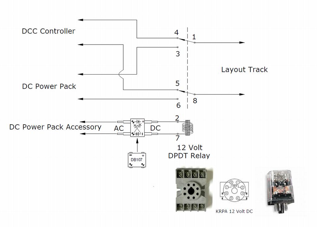
I use a DPDT Relay to switch from DCC back to DC operation. I wire the relay coil to the DC Power Pack accessory connections. Normal operation is DCC, (DC Power Pack off) when I turn on the DC power pack it powers the relay automatically switching the track from the DCC controller to the DC power pack.
The DC power pack accessory output is normally AC, you can use an AC relay but an AC relay has a bit of hum, a DC relay doesn’t. I use a chip rectifier (DB107) to convert the AC output to DC to power the coil on the DC relay.
And thanks MelRR, I remember reading that post or something very like it.
Counterintuitively, it is safer to run DCC as your default or normal mode. Switching accidentally to DC has no risk. If you start out assuming the layout is powered DCC then no DC only locomotives will be on powered track (you will notice the one you forgot by the smoke emanating from the motor location, asuming you failed to hear the buzzing first).
So, normal startup would be DCC unless you accidentally switched on the DC powerpack in which case only DC power would reach the track.
That’s as automatically default safe as you can make a dual mode layout.
Also, using a center off DPDT toggle guarantees that the circuit “Breaks Before Makes”, so there will never be a time when both DC and DCC are applied, even for a split second.
I was under the impression that four wire switches were only used in certain areas of the country where there was no “neutral” wire in house wiring, but two “live” wires that were out of phase, kind of the way 240 volt dryer wiring works.
As electrical code was standardized nationwide at 120 V 60 H the practice of only interrupting the “hot” wire became the way switches were constructed.
Can you imagine the time when local power providers had different voltages, frequency, and sometimes even DC supplied as house utility?
It is physically impossible to get DC and DCC togehter if this is the switch used to isolate the two,. The layout is either goign to be all DC, or all DCC.
Mine was built starting 1914, construction delayed by the War, finished 1919. When purchased it still had its servants’ annunciation board wired up on the back stairs from the dormitory floor to the kitchen.
At that time the house was wired with white (very faded and dirty!) and black fabric wire, all with porcelain and brass 4-wire switches, and all the white wires came down to a big copper bus. There was 240 for stove and dryer on a completely separate set of wires, although I was too young to take note of how the meter was wired in and the service panel was extensively rebuilt with breakers about the 8th time certain fuses cooked off…
Now, the house had been converted to gas heat (with a circ pump so old the makers had no record of what was on its data plate) and had the Cullinan Diamond of early sealed-pane insulating windows, so it is possible that the electrical system had been rebuilt to grounded neutral later. We were promised the house blueprints and construction records but never got them.
My oldest daughter just gutted a 115 year old Queen Anne Victorian.
She sent me pictures of some of the wiring and plumbing they found in the walls. Apparently the house had been rewired and repiped at least twice each. Some of the original components had never been replaced.
DC engines are designed to run on variable 0-12 volts of DC power. More power, faster speed. DCC has a constant 14V AC (or thereabouts) on the track. The high AC power could damage the DC motor if left that way long enough; if nothing else, the engine would go very fast…at least for a while.
Conversely virtually all recent (last 10-15 years) decoders are ‘dual mode’ so can work on DC or DCC power.
DC loco sitting on DCC track won’t take off - it will sit there and buzz until eventually the motor overheats. Digitrax (and maybe still Lenz) can sort of runa DC loco by altering the DCC waveform. it will be noisy and depending on the loco may or may not work very well.
The Bachmann EZ Command will run a DC loco on stretch zero bii as well as the MRC Command which I use to have some years ago with five throttles. All on ebay. Throttle one was for DCC or a DC loco. I use to runder drive 4-4-0’s with N scale decoders and a Winans Camel, DC as a pusher. Yes it buzzed. Open frame motor with fluwheel and mator armature had patitions on it to be more efficient. Roundhouse loco. Wgen I bashed it, never thought of DCC, My bad. Finally got a Power Cab. Retired it. It ran very well.
Good lord Miss Agnes! I logged in to see if just MAYBE someone might have replied to my newbie electrical query. Thank you all for replying. So much good info here, and even some info about historical house wiring! What a bonanza!
I certainly will take to heart all these warnings about not blowing up my old DC engines. I might just get in the habit of physically removing all my DC locos from the layout whenever I want to run my DCC engine (I only have one, just bought it on eBay. It’s a beauty and I don’t want to ruin it: Atlas yellow-box RS-3 custom-painted n the rare, original SP&S “as delivered” livery of dark green and oxide red.)
Randy, yes, THAT is the switch. I love it. It looks like a mad scientist switch, a Dr. Frankenstein switch. Thanks for finding that.
And Kevin, I love that your layout is in “a personal fantasy world of semi-plausible nonsense on Tuesday, August 3rd, 1954.” That’s the same world I’m modeling. What are the odds?
Thanks all for the warm welcome and great info and ideas! I think next I’m going to get a drawing of my layout plan and post it in here and let you guys gnaw on it. I’m sure it can be improved by the hive mind.
DPDT center off works. Make sure you throw the switch to the appropriate system BEFORE you power the system up. This minimizes the chance of a power spike that will fry your DCC system. Don’t ask me how I know this…