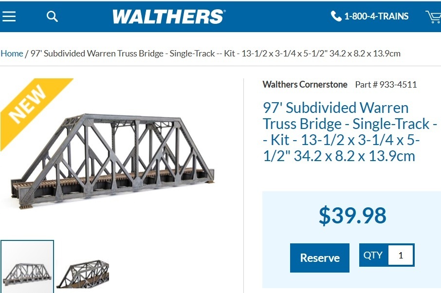
Hi everyone. Walthers’ new single-track truss bridge is called the 97’ Subdivided Warren Truss Bridge (Part#933-4511). I think it’s the Pratt Truss, or more precisely the Baltimore Truss. See the Wikipedia explanation.
Hi everyone. Walthers’ new single-track truss bridge is called the 97’ Subdivided Warren Truss Bridge (Part#933-4511). I think it’s the Pratt Truss, or more precisely the Baltimore Truss. See the Wikipedia explanation.
I agree with you that this new Walthers bridge is an example of a Baltimore (Pratt) Truss bridge.
When I first saw this thread, I decided to research the issue more closely because I know from my model railroad bridge building experience that there is a variety of “truss” bridges. The various designs differ, sometimes if ever so slightly, to deal with issues of load, namely tension and compression.
While there are a few images of Subdivided Warren Truss bridges on the Internet, none are from civil engineering sources, so there appears to be some confusion about the various types of truss bridges. Moreover, the listing of truss bridge types often include the Warren Truss bridge, but not the Baltimore Truss bridge. However, it is generally accepted that the Baltimore Truss bridge is a subdivision of the Pratt Truss bridge, as opposed to the Warren Truss bridge.
For illustration purposes, take a look at this website:
http://pghbridges.com/basics.htm
Since the Walthers bridge cited here is a new entry to be ordered under Reserve status, the instruction sheet is apparently not yet available on the website. It will be interesting to see how Walthers describes this bridge. The usual practice is to identify the source of the design or to at least indicate what design the bridge is based on.
Rich
Certainly there are Warren bridges with vertical members, and if they have 6 panels or more, it is convincing. But the 4-panel is indistinguishable from Pratt.
8-panel example (Modern Architecture watch by sunshine-works)
Here’s a quick photo (cellphone) of a sketch I taped to the wall to keep track of the components I fabricated to build the long-span Win Littlefield Bridge on my layout.
Notice any similarities?


Is this also Warren truss?

PRR X-23 Work Car (Pacific Limited/FM Models 1990, #PL-450)
I would say it is.
The Warren Truss was also used in some aircraft design, either in the layout of the interplane struts on biplanes, or the main fuselage structure on some “rag and tube” aircraft, the Piper Cub being one example that I am reasonably familiar with.
Cheers, the Bear.[:)]
I hesitate to jump in even further . . .
When all is said and done and the humps and bumps and curves and dips and distortions of my little bridge are removed, it can be diagrammed as shown in Figure 1 below, a subdivided Warren truss with 13 bays arranged in a 3-7-3 pattern:

Figure 2 shows a plain old Warren truss.
Figure 3 adds full-height verticals to divide the bays.
Figure 4 adds half-height verticals to subdivide the divided bays.
Figure 5 adds diagonals to produce something that looks kinda like the thing that Walthers is advertising as a ‘Subdivided Warren Truss’ bridge that is the subject of this thread. I suppose controversy arose because the Walthers bridge has only two bays, and that doesen’t seem like enough to develop a clear-cut pattern for proper identification.
Mostly semantics.
Nicely done, Robert. [Y]
Rich
The following image is an OMI Bulletin page published by Canadian Model Trains, which closed in August 2012. Shortening this 6-panel bridge to 4-panel…

Click to enlarge
For those interested in the structural engineering aspects of a Baltimore truss type bridge, here is an excerpt from an older thread posted by the OP.
Almost all of the literature on the Internet about truss bridges fails to mention the Baltimore truss type bridge. Here is an article that does mention the Baltimore bridge.
Hello All,
As I do too, but here goes…
Technically the center section of your span is a suspension type, as the deck is suspended from the structure above through members in tension.
While a fantastic model, it’s not commonly used for railroad bridges.
In the book, Model Railroad Bridges & Trestles, Kalmbach Publishing Co., 2006; pg. 7, it reads:
Suspension Bridges
“…The floor is suspended from these main elements by smaller vertical cables called ‘suspenders’ or ‘hangers.’ Suspension bridges are suitable for distances of several thousand feet. While suspension bridges are inherently flexible and thus not well suited to heavy railroad use…”
Yes, the structure that suspends the deck is a type of Warren truss. As built, the bridge is not purely a Warren type either.
Thank you for sharing your amazing structure.
Hope this helps.
Hey JJ -
Thanks for noticing, and thanks for taking the time to add thoughtful comments. You are right, this type of bridge was never used for railroad traffic. My version is based on a highway bridge in Jacksonville, Florida, with several deviations. I take a very broad view of the freelance part of freelance prototypical.
Winston Littlefield was the lead engineer and project manager for the company that designed and built this bridge in the mid-sixties when I was a kid. I later went on to work for his company as a rookie junior draftsman, and everyone there called
[quote user=“ROBERT PETRICK”]
jjdamnit
Hello All,
ROBERT PETRICK
I hesitate to jump in even further…As I do too, but here goes…
Technically the center section of your span is a suspension type, as the deck is suspended from the structure above through members in tension.
While a fantastic model, it’s not commonly used for railroad bridges.
In the book, Model Railroad Bridges & Trestles, Kalmbach Publishing Co., 2006; pg. 7, it reads:
Suspension Bridges
“…The floor is suspended from these main elements by smaller vertical cables called ‘suspenders’ or ‘hangers.’ Suspension bridges are suitable for distances of several thousand feet. While suspension bridges are inherently flexible and thus not well suited to heavy railroad use…”Yes, the structure that suspends the deck is a type of Warren truss. As built, the bridge is not purely a Warren type either.
Thank you for sharing your amazing structure.
Hope this helps.
Hey JJ -
Thanks for noticing, and thanks for taking the time to add thoughtful comments. You are right, this type of bridge was never used for railroad traffic. My version is based on a highway bridge in Jacksonville, Florida, with several deviations. I take a very broad view of the freelance part of freelance prototypical.
Winston Litt
This video is a load test of The Great Seto Bridge when it was completed in 1988. As you know, this bridge is a road/railway suspension bridge (Wikipedia-English). It announced that it had sunk 31 inches (80 centimeters) while running a 1,000-ton gross train. 5 minutes and 30 seconds after the start…
Hello All,
Thank you for your insightful, respectful, and considerate response to my laypersons’ observations.
Your structure is a feat of model engineering and shows a level of detail that I can only hope to rise to.
I didn’t mean to detract from your skills, I only hoped to enhance the conversation.
My father is a retired architectural draftsman- -before CAD.
I appreciate your technical and artistic skills and please keep sharing your knowledge, craft, and imagination with us all.
Hope this helps.