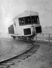
That is the Brennan monorail, patented in 1903 and demonstrated in 1909. The advantage claimed was that it was useful for a military railroad since track could be laid quickly. The 1962 version was by Swinney and looked more like a rocket.
Now the next item of business: how to build a model of it, and, specifically, how to power it. Two rails would seem to be the minimum for an electrical circuit; but I think we can do it with one:
Make the conducting surface of the rail in segments, for example, 3/4 inches long, with a little plastic in-between so that a wheel doesn’t short two adjacent segments together. Power alternate segments with the two wires of the transformer circuit. Put a pickup assembly on the monorail vehicle with three fingers or rollers spaced 1/2 inch apart. We can show that one side of the circuit will always have two fingers and the other side will always have one. Connect each finger to two rectifier diodes, one pointing from the finger to a positive node, the other pointing from a negative node to the finger. Those two nodes are the rectified DC source for the motor (and e-unit). Put at least two such assemblies on the monorail vehicle, as far apart as possible, so that any necessary break in the rail-segment pattern affects only one of them at a time. The fingers can also have other spacings, such as 1 inch and 2 inches. With luck one of these spacings will match the wheel spacing so that we can use the wheels instead of fingers.
That is pretty brilliant (but we expect no less from you, Bob!) However, what do we think of using catenary? It might not be prototypical, but it would be cool. That way, you could have your two separate power wires-one in the rail, one in the cat. That still doesn’t help in keeping it upright, though…