Hi, Ive been avoiding wiring this antique MRC three way turnout because I was considering replacing it but it works fine and 4 wheel locos go right through so I decided to wire it to the control panel.
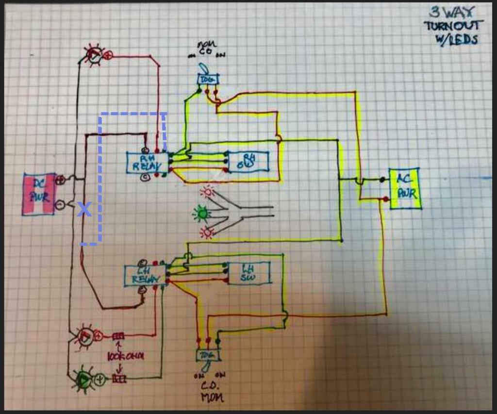
Someone who knows how to do this please take a look and tell me if I have it correct. Note that there is ONE Green LED Wired from ONE of the relays. The intent is for the green to light when the path is straight,
hard for me to tell, i don’t know what the pins on the relay blocks are
i think the relays may be avoided by using the switches to provide a path to ground. The ground to both the DC and AC supplies can be connected together so that the connection to ground can route power through both the turnout motor and LED. since a ground path is being made, it doesn’t matter that the two power supplies are different voltages or AC and DC.
i assume the 3-way turnout is effectively two turnouts in series. the one switch provides a ground to the lead turnout, providing power to the turnut motor and LED for the diverging in position and NOT providing a ground connection to the 2nd turnout.
when that lead SPDT switch selects the non-diverging route, the SPDT swtich provides a ground to the turnout motor for the non-diverging path and the 2nd SPDT switch which either selects the straight path or the 2nd diverging path.
the two SPDT switches provides a ground path for each of the three routes which provides power to a only one of the three LED.
Ok I can use 1 resistor. I know I need the relays using SPDT CO Momentary toggles.
The toggles and switch machines are powered by AC and the connection is “momentary” then it’s disconnected so even if I could power the LED’s from the switch or toggle with AC they would go out. The Relay contains 2 SPDT switches which are thrown to teh correct position when the Momentary toggle is switched. They stay in that position until the switch is thrown the other way. They are powered from a DC Power source.
My only remaining question is do I need to power the GREEN LED indication the through route from BOTH switches on the three way or just 1 as shown.
I’m having problems with my forum access since I changed my email. So I posted my reply on my new email which needs a moderator because the site thinks I’m new. [:(!]
at this point what I’m asking is do I need to connect both switches to the GREEN LED indicating the through route, or is it good as shown on the diagram.
The snap relays are needed to provide constant DC power to teh LEDs. When the switch is thrown, (AC) it throws the SPDT switch in the relay which is DC and powers the LED.
It should work with the rerouting (blue dashed line) shown in your drawing in my earlier post above. As Greg mentioned above a single resistor in the main DC line or add a resistor to the top LED.
Thats interesting. I see there is no common (DC+) feed to the LH Relay in your blue line edit. Does that mean that the LH relay is only energized when the RH relay switch is powering that terminal (
In your original the bottom relay will have either a red or greed LED on all the time. By changing the bottom relay feed wire from the top relay the only LED on with be the position of the turnout.
I’ll draw a driagram and paste it to this one in a bit.
now that I see what the relay is, i agree with Mel.
i assume the 3-way turnout is two turnouts back-to-back. the first on, with the points closest to the end of the turnut, routes either a diverging route or straight. The straight route leads to the 2nd turnout which can either diverge in the opposite direction or route straight, the middle route
based on Mel’s change, the top circuit in the diagram is the first turnout. DC+ goes to the common terminal of the relay. I would suggest putting a single resistor (1k) in series with DC+ and the common relay terminal.
For the first trunout, the LED should be connected to the relay terminal that is connected to the common terminal when the diverging route is selected. The other relay terminal should be connected to the common terminal of the 2nd turnout relay.
For the 2nd turnout, two LEDs are connected to the non-common terminals of the relay. Presumably a green LED is connected to the relay terminal corresponding to the straight (middle) route thru the turnout.
The anode(+) of the LEDs are connected to the relays. The cathodes of all the LEDs are connected to DC-.
only one LED will be lit. The relays route DC+ to only one LED.
Ok, like I said I haven’t seen a 3 Way turnout but I think you were very close. The drawing below should work OK. Sorry for the delay but I get slower on my CAD by the day, it’s called old age.
Click on the picture to enlarge it. I could email a PDF if you need it.
EDIT:
I forgot to add that the circuit doesn’t accurately display the correct rail position. Looking from top to bottom the bottom LED can be off and one rail not in the correct position for the opposite diversion.
Mel. “You need to make sure you set both switches to sync the LEDs to the turnout.“
I think you mean I need to place the turnout switch wires on the correct terminals so that it all sinks up. I can do that by just switching the terminal that the red or green wire is on. Is that what you mean?
No. I think if you don’t set the turnout to straight after going left (bottom relay) when going right (top relay) the bottom relay and rail are in the wrong position and it’s derail time but the LED position shows correct, either right-straight-left.
I looked around to find a 3-way turnout to make sure but couldn’t find a good description or picture of how the 3-way turnouts work mechanically.
Just make it a practice to always return to straight.
As I suspected the turnout needs to be returned to center to sync the LEDs for proper operation. You would need to do that even without the LED indication. The problem is the LEDs could miss lead you if you don’t. The top LED can be on with a rail in the wrong position.
I guess I didn’t say it correctly. Yes you are correct Greg. There will be only one LED on no mater which direction the turnout is positioned. But unless the SPDT switches are returned to straight there is a possibility of the left diversion rail being open when the right diversion is selected. Setting the turnout to straight first closes the left rail.
Complicated to explain but the first time it isn’t set correctly will point out the error with a derail, but the LED indicator said the turnout was OK.
The simplest fix for me would have a seperate toggle for each direction using DPST momentary switchs, the second half of the DPST switches operate the corect switchmachine/relay direction. That way it would be flawless.