what brand/model turnout?
they might be power routing and just need some insulated rail joiners on the rails from the frog
what brand/model turnout?
they might be power routing and just need some insulated rail joiners on the rails from the frog
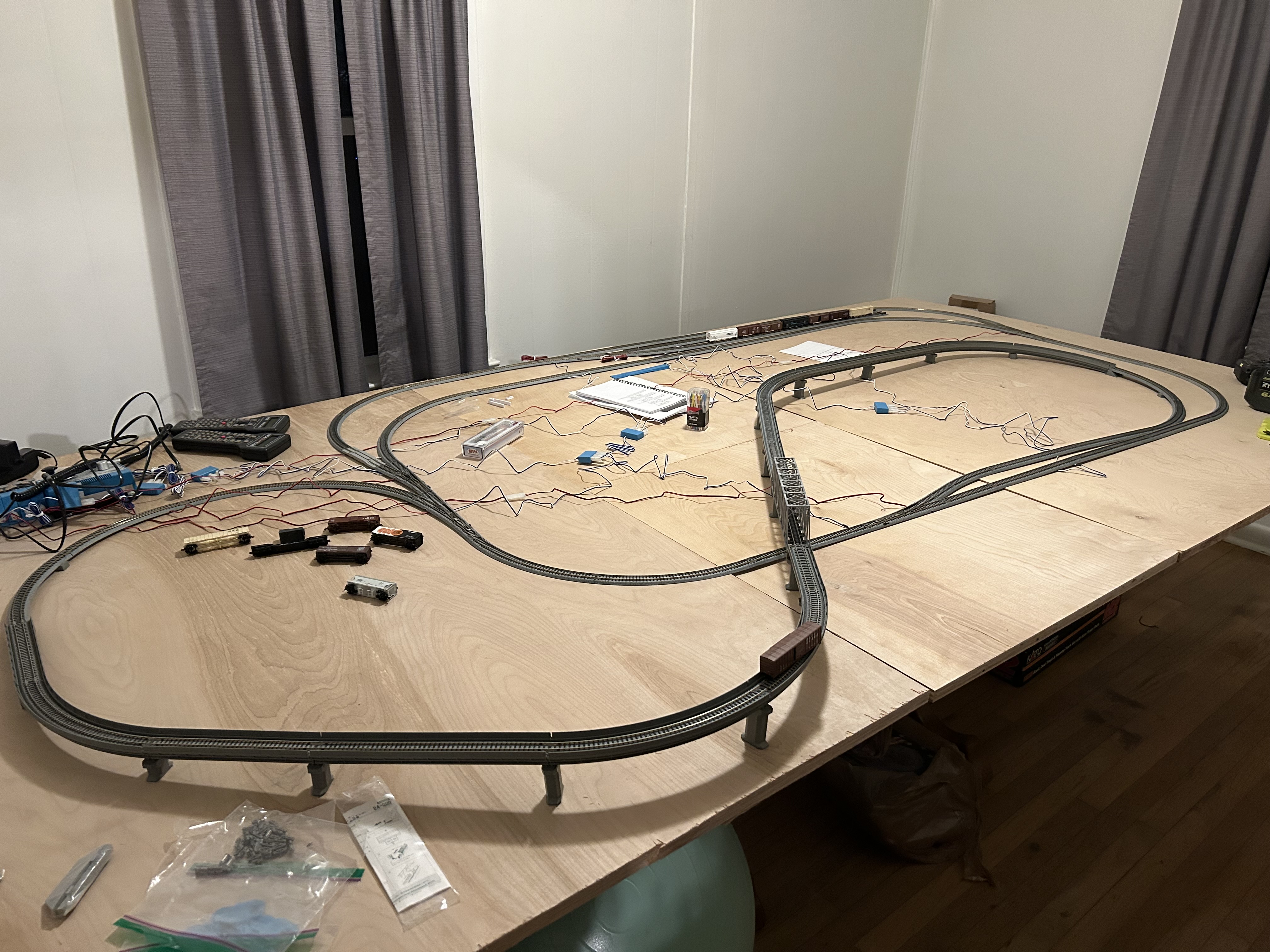
Do the bottom of your turnouts look like these?

Back when I had Kato N Unitrack all the turnouts were ‘[power routing’ meaning that IF two turnouts faced each other as your double-end siding shows, you HAD to have an insulated joiner in at least one rail between each frog of the pair of turnouts.
This is a necessary evil of wiring ‘power-routing’ turnouts. The alternative is the ‘all live’ turnout which has an insulated frog and each route of the turnout is powered with the correct polarity regardless of the way the points are thrown.
Kato makes insulated joiners for their Uni-track.
Good Luck, Ed
Its all Kato tracks.
I have insulated Kato joineres. Have not done anytyhing wityh them thinking I didnt need to change anything,. So if I have the 2 turnouts where do I have to put the insulaters
If you use the insulating unijoiners, you’ll need to add power to the now-isolated track. I use Kato’s power joiners, rather than feeder tracks.
Forgive me for i am not sure what your saying. I have a piece of kato track that has leads to each rail what am i not getting? Just get rid of it and simply solder wires to each side of rail on any track? And you mentioned the kato insulated joiners. Where am i supposed to use them as i have them in my supplies. I just figured it was like when i set up a dc track as a teenager i had one track with wire to each side of track and it worked. Turnouts i had as well with switches. Did things change? Or am i not explaining myself correctly. Confused…
Kato’s power-routing turnouts only supply power to the “active” route. Approaching a turnout the “wrong” way will result in a loss of power to the locomotive.
Kato sells joiners that have power leads already attached. You remove the existing unijoiners and replace them with the power unijoiners. (I tried searching the web, but I only found vendor sites, not stand-alone pictures.)
Similarly, remove the existing unijoiners from the turnouts and replace them with the insulating unijoiners.
The more I think about this, the more convinced I become that the current ‘problem’ is that the turnouts are routing power.
The talk of insulating unijoiners and power unijoiners is orthogonal to the actual solution: making sure both turnouts are lined for the path you want the train to take.
Later on, when you build that second layout, you MAY need additional feeders, depending on how many trains you want to run at the same time.
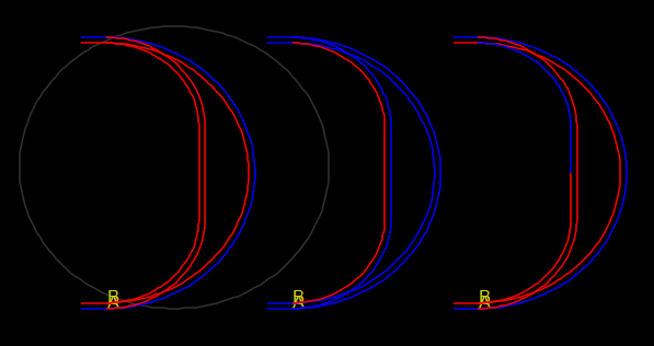
power routing turnouts make the frog and the adjoining rails the same polarity depending on which rail the points are in contact with. This means the the inner rail of the non-diverging track and the outer rail of the diverging track are the same polarity.
when both turnouts in the photo are aligned for the non-diverging (straight) route, both rails of the inner- curve have the same polarity, the same polarity as the inner rail of the outer-curve
and when both turnouts are aligned for the diverging routes, both outer-curve rails have the same polarity, the same as the outer rail of the inner-curve
but when both turnouts are NOT set the same, one diverging and the other non-diverging, there is a SHORT !
i believe the solution is to put insulated rail joiners on both rails connected to the frog of each turnout (4 insulated gaps).
and the inner rail of the outer-curve and the outer rail of the inner-curve need separate feeders (assuming that the main power connections are elsewhere)
Given the simple track configuration, that would seem to make the most sense.
Rich
what brand/model turnout?
they might be power routing and just need some insulated rail joiners on the rails from the frog
Bingo!
Times like this, I wish I owned a multimeter and knew how to use it.
I think you are wrong, gregc. With Kato, the unaligned track is dead, no power at all.
According to the fine print at https://katousa.com/wp-content/uploads/2022/01/HO-Unitrack.pdf I’m right. Still, I wish I could test with a multimeter.
They are Kato. When using insulated rail joiners, which I did get, which rail should it be on
can you used an LED to check the if there is voltage on the rails leading to the frog and what its polarity is?
Wow… I picked up a Astroai multimeter on amazon aand boy is it diffrent than what I had as a kid. Super involved. Instructions usless. How do I set it to simply measure DC current to my tracks… Help
while voltage simply requires putting the probes on 2 points, to measure current , the meter need to be “part” of the circuit so that the current flows through the meter. In this case between one rail of the track and the corresponding terminal of the DC throttle
one probe is the common, the other probe needs to be moved to the 10A connection on the left. if the current being measured is < 0.5A, you can use the uA/mA connection. an internal fuse will blow if > 0.5A
and set it to A, ma or uA.
As I recall, you are initially operating in DC. The manual is clear. Test for DC voltage, not current. Place the tip of each probe on a separate rail. You will get a reading if polarity is different on each one of the two rails probed. If you get no reading, or a very weak reading, the polarities of both rails match, indicating either a wiring error or the need to gap the rails.
Rich
Thank you but still not easy to use as instructions arent very clear. I dont know what setting to put it on nor where the red or black goes for varios settings. And now OMG i tried using my NEC DCC controler and intial start up i had loco on track and it respoded to whistle and horn and moved. I tried to set up loco number and nothing works. I googled factory reset and now loco does nothing. How can i reset loco or whatever to respond. I hope you have DCC experience
have you tried making a simple voltage measurement? to measure DC voltage, turn the knob to the V with the straight bar. to measure AC voltage such as DCC, turn the knob the the V with the wavy lline. With the knob set, put each probe on a rail of the track
a Factory reset does reset the loco to address 3