I am having trouble with the Walther’s 90 ft. HO turntable radial track wiring. This is the second incarnation of the turntable that is DCC with indexing controller. I have read the thread from 2011 on this forum where some say that an auto reverser is needed and some say not. I am in the DCC camp that it does need one because of the following scenerio.
Here’s the issue. All of my radial tracks are wired to the same bus the same way on its own DCC Specialties circuit breaker. This means all of the radial tracks are wired the same all the way around. The Walthers turntable receives power from another bus. I have 17 powered stall tracks. From position 1 on the controller which is stall track 1 on the DCC controller to stall track 11 all works fine. Both ends of the turntable work just fine. These are all on one side of the Walthers split rail DCC design ring located on the bottom of the bridge. The lead in tracks, of which there are three, are on the same side of the split rail. When I get to track 12, which is on the other side of the split rail design the, ALL of the remaining tracks short when an engine attemps to go on these powered track 12-17 (six tracks) when either end of the bridge is aligned with these tracks. Why would this happen? Wiring has been quadrouple checked and I am pretty DCC savy but I cant figure this one out. The turntable has been in service for a year with no powered radial track and was used just to turn engines. I have now added the powered radial tracks because I am at the punch list area to work on my engine facility.
It is not advisable to put the Auto Reverer on the radial tracks. It is more advisable to put it on the bridge. Would it be better (and I think I just may have solved my issue with this) power the turntable from the same bus? Or install an auto reverser on the existing wiring to power the turntable from the bus?
You answered your own question “on the other side of the split rail” - the split rail power to the bridge reverses the polarity of the bridge track when you go past it. So now the polarity of the bridge rails does not match the polarity of the stall tracks. Easiest solution is an autoreverser to the bridge rail power. Power it fromt he same bus that powers it now, no need to rework the whole thing, although some people find it useful to put a switch on each stall track to kill the power so a) you don’t have a dozen engines all sounding off at the same time when you turn on the power and b) so you don’t accidently select the wrong address and drive an engine into the turntable pit.
I wired the turntable into the same DCC specialties circuit as the radial tracks. Same results. So the issue is not being wired into two different bus power lines. The same tracks short the turntable and controller shuts down until the engine is moved off of those tracks and it resets. I think the problem lies with the other half of the split ring design of the Walther’s turntable. Bill
Thanks for the quick reply Randy. I did put the turntable on the same circuit breaker as the radial tracks (See post below) I got the same results. I will have to get an auto reverser module. Thanks. Bill
Older threads from both 2010 and 2012 discuss a similar problem. When the turntable crosses the dead zone, the polarity of the turntable is reversed. That is the way it is supposed to work, not a design flaw.
I think it would also work if your reversed the wiring of tracks 12-17. However the orientation of the bridge would have to be constant. In other words if the train entered from the approach tracks with the TT shack on the far side of the bridge, it could only re-enter the turntable from the radial tracks if the shack was closest to the radial tracks. An auto reverser allows the bridge to be in any position, ambidexterous?
Randy am I wrong? In real life polarity is not an issue
Randy and Henry. That will not work as ALL the radial tracks are wired to the same bus line. The problem is when the bridge crosses the "dead zone’ and flips polarity it causes a short from the bridge tracks to the radial tracks even now that I connected the turntable to the same bus line as the radial tracks. The design of the split ring turntable circuit is the issue. It is working as designed I guess. But it turns out not to be a good design for the radial tracks beyond the split ring on either side. One side will work the other shorts. It makes more sense to put a AR on the tunrtable bridge track then on all of the other tracks. Sometimes just talking it over with someone else helps figure things out. I think the design of the split rail, even though it works in theory, doesnt work in practice with a large number of radial tracks. Thanks guys. Bill
But each radial track needs at least one set of feeder wires, otherwise it doesn;t have power. Swap the rail A and rail B feeders for just the affected track.
Each track does have its own pair of feeders all from the same bus line that is independent of the surrounding tracks and on its own PSX circuit breaker. I guess the point is that I shouldnt have to as they are all wired the same. It is the Walthers split rail bridge track power that won’t shift the polarety the to match the track. I don’t understand why it won’t. I have an email into Walthers but nothing yet.
It won’t shift, there’s nothing to make it shift. If you have all the stall tracks wired (going clockwise): AB,AB,AB,AB,AB,AB then you will get a short on the two after the split. You need it to be wired AB,AB,AB,AB,BA,BA
There were choices to be made. They could jack the price up and supply an electronic reverser (and we have seen a lot of difficulties in the forum wiring these correctly to work) or they could reverse the bridge mechanically using the gaps. With a straight bridge, gaps only work 180 degrees apart.
They figured most people would be modeling less than 180 degrees of storage rather than something like this:
Things must have changed. I have the original ‘built-up’ model that was indexed, but not DCC, issued around 2005/2006. I didn’t have to do any accommodating wiring to either the lead or to any of the three radials. They all had the same polarity. If I reversed the loco, it either backed or moved forward into the radial bay tracks. No reverser required in either case.
Yes but are all your radials ont he same side of the “no track here” zone, or split across? I think the OP has some on each side, and the “no track” zone is where the bridge reverses.
I had a similar problem with the Walthers non-DCC 130’ turntable.
In addition to 9 stall tracks, I had two approach tracks, one coming from the north and one coming from the south. The polarity of both approach tracks matched. Yet, I would get a short every time that the bridge aligned with the south track. I could never figure out the probem so, in desperation, I isolated the south approach track and added an auto-reverser. Problem solved!
Then, in October of 2010, I started a thread to see if someone had an explanation. Here is the link to the thread.
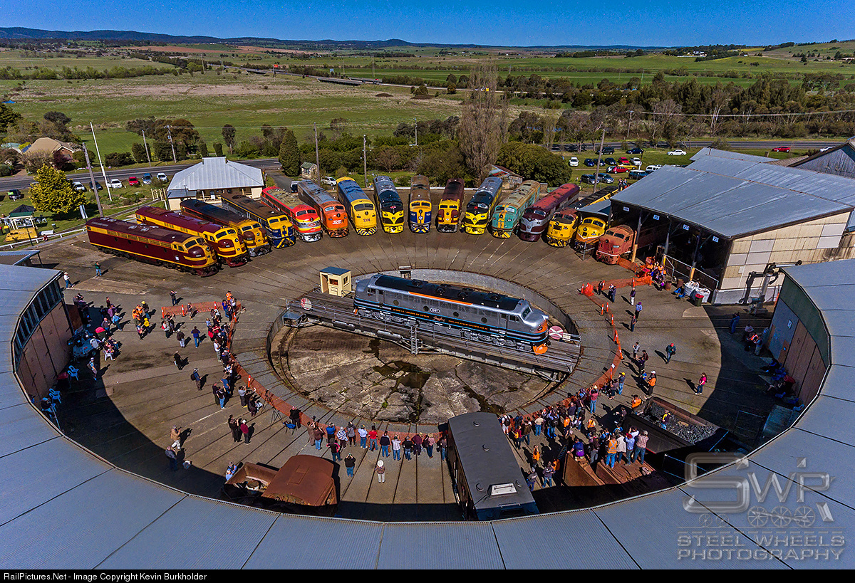
The answer to your problem is in the text of your last post. The ‘dead zone’ is at 9 o’clock under the yellow crane and straight across between two tracks at 3. Your approach tracks are at 8 o’clock and 4 o’clock. That puts both approach tracks on the same side of the ‘dead zone’. On the left 8 o’clock approach track the red feeder is closest to the 9 o’clock dead spot and on the right track 4 o’clock the blue feeder is closest to the 9 o’clock dead spot.
Hence both approach tracks approach the same half of the TT with the feeders on the right approach track reversed in relation to the left approach track. A short every time.
The dead zone divides the TT into two electrical components. All tracks approaching each half must be wired the same. If the ‘dead zone’ (no-track) was between the roundhouse and engine shop you would have no reversing issue. Probably not worth the effort to rotate the TT or re-route the right approach track to be at the 2 o’clock position, either of which would eliminate the reversing issue.
Yes, Randy, you are right. I had all three radials opposite the lead. If I had reversed the loco and backed it into a radial that happened to be on the same side of the dead gap in the split ring as the lead, I could see having a conflict in phase or in polarity.
After the Bronco/Chiefs game I went down and cut, moved and put in wires. The turntable, controller and stall/radial tracks 1-11 and the lead tracks on the 'north side of the split rail are on one bus circuit with protection (PSX). The other radial tracks 12-17 are on another bus circuit with the bus wires changed opposite of the rest. It works now with both ends of the bridge and no shorting. I will still have to put another circuit breaker on that bus but I’ll do that tomorrow as I have to solder the wires to the circuit breaker before I install it. Thanks guys for all the suggestions and comments. It is working like it should now. I will talk with Walthers about it and see if I have to send my controller in, but if it works, why mess with it? Bill
Congrats, I guess, but I am not sure that I understand how you got things to work right with that wiring arrangement.
For me to get my situation to work, I needed to isolate that one approach track and create a separate reversing section. I cannot see how configuring feeder wires on a separate sub bus will do the trick.
Are you using two boosters? Even then, wouldn’t the two boosters need to be wired in phase?
Maybe I am mistaken, but it seems to me that there was some other problem that got somehow corrected along the way.
You can feed the ‘reverse’ wired tracks fromt he same circuit breaker, you don;t necessaily need another one. The admonition to keep the feeders all the same applies for continuous track that is all physically connected, reverse a feeder there and you have an instant short. These individual segments are isolated from one another so all of them can be fed from the one breaker.
Rich - what he has done is have some stall tracks on one side of the no track zone and some on the other. Not across the pit, diametrically opposed, but as you are going around the table, there are tracks, the dead zone, and a couple more tracks. When the table passes the no track zone, it’s crossing from one side of the split ring to the other, so the table polarity changes (without spinning a full 180 degrees). There is apparantly not a lead in track across from those few extra stalls, or there would be a similar problem to yours in that the bridge would either match the lead in, or match the stall, but never both so you could drive right across. In the OP’s case, he can drive on to the table, spin it to one of the first 11 stalls and it worked fine. Spin a little more to track 12, past the no track zone, and now the bridge polarity has reversed but since the stalls were all wired with )for example) left rail black, right rail red, there is now a short trying to get on the stall track. Flipping the feeders to the stall takes care of this. Pull off one of the higher stall tracks, now spin the table back counterclockwise to line up the lead track, and again you pass the no track zone, the polarity of the bridge flips, and you match the lead in (and those first bunch of stall tracks).
Randy, it just dawned on me that he has isolated the “reversing sections”, if you will. Because they are stub ended tracks, they are effectively isolated. So, when he flipped the feeders, he eliminated the shorting situation.
In my case, that south approach track had been connected to the main line before I isolated it, thereby creating the short.
As I think about it, it seem that the Walthers split ring turntable, as well as it is designed, is flawed in that it is possible to create shorts in the absence of a true auto-reverser.
Suppose you want to send the engine back out to the mainline facing 180 degree opposite the direction it entered. Is there a switch on the controller to permit this or would you still need an auto reverser or DPDT switch on the turntable feeders?