I’m putting in a wooden truss or arch bridge that will be on a 3% grade. There is a diagnoial track below it so a trestle bridge won’t work. The bridge will need to span about 12" long HO).
So my questions are:
Should the truss bridge be built on a slant along with the 3% grade?
And if so, would the truss members still be vertical?
Or should the bridge be built on the level with only the track on it rising with the 3% grade as it crosses the bridge?
I see, so that’s how it is. Each panel of the truss is made into a parallelogram!
There’s no way we could understand it just by looking at the exterior.
While the 3% grade is pushing the boundaries, it is just one of the compromises that model railroaders often have to make.
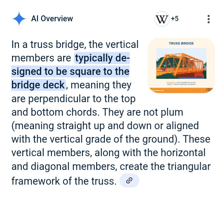
That drawing of the C.P.R Bridge 41.2 is interesting because from the little I’ve read; with truss bridge construction the verticals should be perpendicular to the horizontal.
When building a bridge, I found it to be challenge enough. When finished, the entire bridge was installed with the grade, so they weren’t horizontal and vertical anymore.
To tell the truth, it’s very difficult to tell just by looking at the layout.
For me, it would have been major work trying to get the bridge sections and the grade figured out and built to fit. The bridge was hard enough as it is.
There are two considerations here with truss designs.
First, the arch is much better suited “if your railroad can afford it” because it inherently solves any considerations of weight transfer and thrust. So we get that out of the way.
Trusses have to be made to accommodate expansion and contraction. Therefore you usually see them mounted on ‘shoes’ or rockers at at least one end, The assumption is that the resultant of forces in the truss will resolve vertically in these shoes.
Thrust from acceleration or braking complicates this. On the level this is considered small compared to the Cooper rating, and may be handled in the rails or as horizontal ‘buffing’ surfaces, but as soon as you introduce grade there is a gravity component displacing the track as well as augmented lateral force on the downgrade end. If you have a ‘fixed’ end of the bridge it probably makes more sense to incorporate the horizontal anchoring there, which would be at the bottom, and arrange the shoes to be vertical-bearing at the top.
Skewing the panels so the ‘vertical’ members are vertical will help equalize the static tension and compression loads in the truss structure. I don’t have enough patience to go through and calculate the imbalance for 2 or 3 degree grade (which is 1 to 1.5 degree inclination) but my estimation is that the factor of safety in design probably outweighs the racking tendency.
I am going to be building a freelance model of this curved bridge on a 1.7% slope. I don’t think there should be any issue with the slope, but I guess I will find out.
Indeterminate structure: a continuous plate girder bent to curvature, with adequate bent support. Would be interesting to see the detail drawings of how the top members of the bents tie to the girders, and how the bridge is anchored at the endpoints.
Indeterminate structure: a continuous plate girder bent to curvature, with adequate bent support. Would be interesting to see the detail drawings of how the top members of the bents tie to the girders, and how the bridge is anchored at the endpoints.
I thought that all those intermediate structures were always straight girders with just the track/tie structure making the curve.
When the deck girders or trusses are separate panels, as they usually were for fabrication reasons until recently, they are better made straight, with the width sufficient to carry the track curvature and the bents designed for the angle and any resultant thrusts. There are some Japanese curved-truss bridges that we discussed in a previous thread on the ‘old’ forum.
When the girders can be welded into the equivalent of continuous beams, as here, you have the effect of a horizontal arch, with lateral track forces carried radially outward. It would be an interesting structure to analyze statically and dynamically.
I don’t know about horizontal or vertical forces, but I am going to start with the Micro-Engineering 75-515 - HO Tall Steel Viaduct, Standard Bridge, 210’ long as the base structure and see what I can concoct.
Those are really good questions Jim. The same one’s that were also pondered by me quite a few years ago building bridges. I’d have to agree with a few others here.
The water is of course level along with the highway bridge. So it clearly displays the railroad truss bridge with a definate grade. Looking at the center pier support, it’s easy to see, the vertical members are not plum.
Bridges also have rotation, along with expansion and contraction that must be accounted for with bridge shoes.
consider how a bridge works. lower longitudinal members are in tension as they are pulled when weight it applied to the bridge, and the upper member are in compression.
the vertical and diagonal members are keeping the longitudinal members parallel to one another.
so the briges exists as a unit, regardless if parallel to the ground or not.