Locomotive: USA Trains EMD GP30
Stock PCB (brain): YD-249-PCB-01
Planned control: RailPro LM-5S-G with sound (hard-wire install)
What I’m doing
I’m replacing the factory electronics in a USA Trains GP30 with a RailPro LM-5S-G. Goal is simple, reliable motor control + lights (and possibly smoke later). I have the LM-5S-G manual and understand the basic RailPro wiring (track/battery power to PWR +/-, motor to M +/-, lights to function outputs).
What I’m seeing inside the GP30
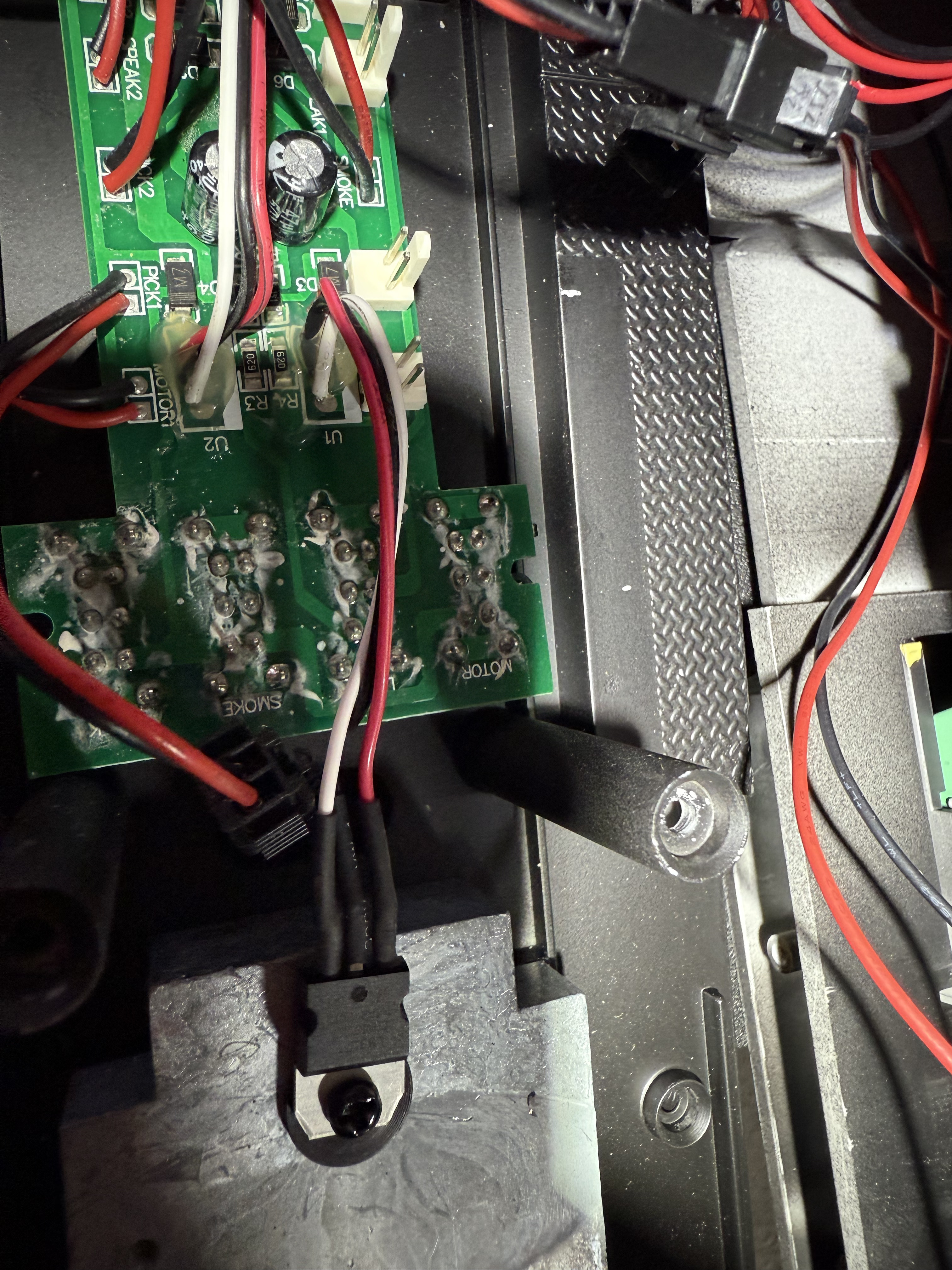
Each motor truck feeds the stock PCB with three wires: black / red / white. On the PCB those 3-pin plugs are silkscreened U1 (one truck) and U2 (the other truck).
My questions
- What are “U1” and “U2” actually for on this USA Trains board?
- What does the third (white) wire from each truck do? Motor blocks usually only need two wires.