I’m thrilled to report that after getting my mainline loop running (minus turnouts to yard, siding and branch) and running my DC locos on it for a few weeks, I finally ventured to hook up my NCE Power Cab starter kit and was able to watch my DCC locomotive light up, sound off, and come to life. It worked beautifully, and I’m very happy because I bought the engine (SP&S custom painted Atlas YB RS-3 fitted with DCC) almost a year ago and only saw it operate once in a hobby shop I took it to.
I bought the NCE Power Cab Starter kit at the same time, new. The wheel on my throttle doesn’t quite make a smooth increase or decrease in speed – same issue as the member was having here – which is a bummer and I’ll have to act fast if I want it fixed under warranty, but I’m not really that bothered about it. I’m just thrilled to run that engine and have it make so much wonderful noise.
Why I’m posting – I originally interrupted the wires to the track with a little switch, so that I could leave my DCC cab hooked up while also continuing to run my DC stuff, but the DCC loco wouldn’t budge or make any noise with the switch there. I removed the switch and just twisted the track wires directly to the wires from the DCC unit. That worked.
So my question is, why didn’t it work with the switch in? Was it because it was a SINGLE pole double throw? Should it have been a DOUBLE pole double throw?
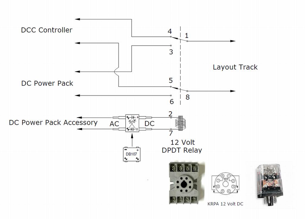
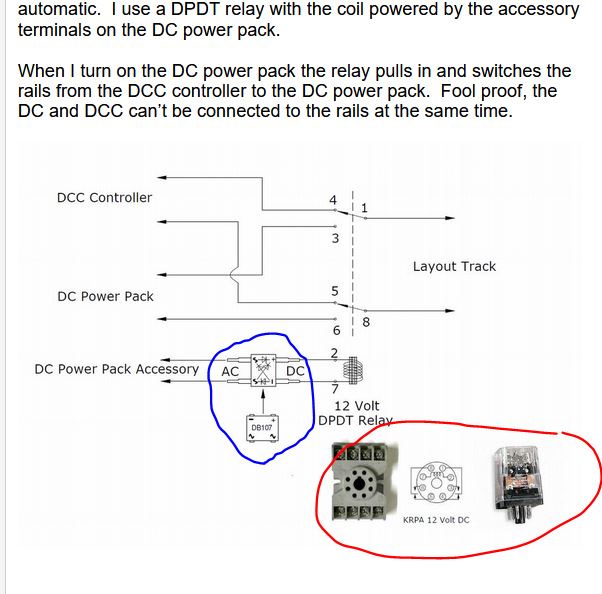
I run dual mode, DC or DCC and made my connections to the track automatic. I use a DPDT relay with the coil powered by the accessory terminals on the DC power pack.
When I turn on the DC power pack the relay pulls in and switches the rails from the DCC controller to the DC power pack. Fool proof, the DC and DCC can’t be connected to the rails at the same time.
Mel
Modeling the early to mid 1950s SP in HO scale since 1951
@mel, I think you’ve told me this before when I was asking how to set this all up before I was really able to absorb all the helpful information. I like your method a lot. I’m not good with electrical diagrams but I think I understand most of your illustration. The numbers connections at top correspond to the numbered holes in the relay. The only part that I don’t get is the item midway along the bottom wires …numbers 2 and 7. Is that the coil you mentioned? What are the exact products you used, both for the 8-hole relay and the AC/DC coily thing?
BTW, right now there are just two track wires. I have purchased 14-gauge stranded wire for a pair of bus wires under the mainline, and 22-gauge wire for feeders, but have not installed them yet. The loop is small enough that the tiny feeders that came with the power pack do a fine job and locos don’t lose power even at the far end of the layout. But I do intend to install a bus-wire system and feeders.
I’m surprised nobody mentioned the need for a way to remind you never to connect the DCC power if there’s a DC powered locomotive on powered track.
The other way around is not a problem.
Also, only dual mode decoders will run on DC powered track.
Even dual mode decoders can be programmed to ignore a DC powered track for technical reasons related to possible runaway conditions. If a dual mode decoder equipped locomotive won’t run on a DC powered track check that DC mode (analogue) has not been disabled. You need to use the “look up” chart in your DCC decoder manual to find the CV number and the value you need to enter to switch the DC or analog mode on or off as desired.
Be VERY careful. You really don’t want to wire these dual-system things wrong. Not only won’t they work, but they might never work again. You must not ever have the systems connected electrically, ever.
My suggestion is to have one and only one outlet for both DC and DCC. That will force you to unplug one system before plugging in the other. The DPDT switch should work properly, but the belt-and-suspenders approach gives you an extra level of protection.
Mr. B is correct! I’ve been using the relay method for many years (14 yrs) and so far I haven’t dinged anything but a newbie might not be so lucky. Being conscious about not having a non DCC locomotive on the track when using DCC could be bad.
Using a plug to switch power packs is much safer but you must still to be conscious of what is on the track!
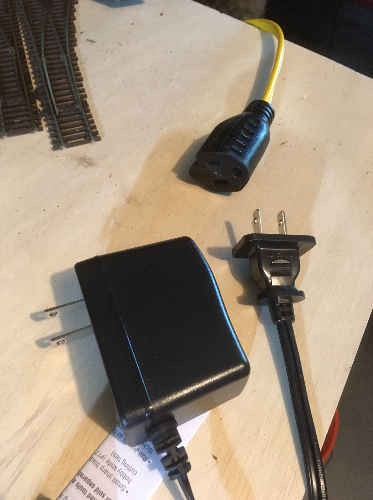
The DCC Power Cab power is lower left, the DC power pack is lower right. Outlet is at top. Only one of the plugs can go in it, so I’ve satisfied your second injunction. But as for the first, I’m not sure. The systems are connected electrically through the DPDT switch, aren’t they? What happens if I have the DC power pack plugged in and a DC engine on the track, but I accidentally throw the switch to the DCC side, or vice versa? Maybe I have my DCC loco on the track and the DCC cab plugged in but accidentally throw the switch to DC? I thought the DPTD was supposed to protect my systems by making those connections impossible at the same time.
Incidentally, until I have a much more sophisticated system and much more track laid, I only ever have one engine out of its box at a time. After a run, I take it off the track.
Mike, I don’t know what kind of decoder is in my engine. I got it used on eBay. It was an old Yellow Box Atlas (Japan I think, or China, not Roco) that had been fitted with DCC. I didn’t really want to try it on DC at first because I had a power pack that seemed pretty “pulsy” and I’d heard that that can blow the brains out of a DCC engine. I finally got a MRC Power Pack that would supposedly be safe, but I’ve seen long threads about this that make my head spin.
Now that I reflect, i think I recall that I gave it a quick test and the engine wouldn’t respond to DC even from the newer MRC power pack.
Mel, thanks in advance for your continued patience. (I did warn all of you that I am a complete ignoramus when it comes to things electrical.)
So if I’m reading you correctly, I would hook up my MRC Power Pack so that its DC wires went to connectors 3 and 6 on the relay, and its AC connections went to 2 and 7 on the relay, but with each of those lines (2 and 7) being interrupted by two prongs of the bridge rectifier. And then my DCC cab would have lines going to relay connectors 4 and 5, and the track wires would come in at connectors 1 and 8.
Am I getting that right?
And that setup enables you to simply plug in your DC pack to switch it over from DCC automatically?
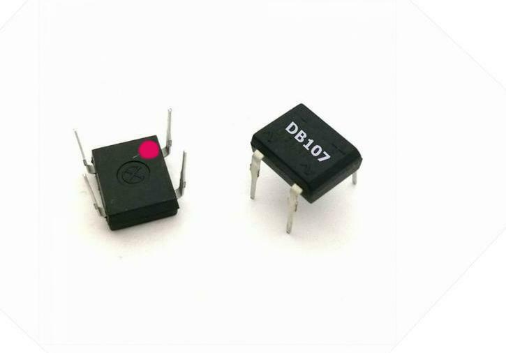
The AC is changed to DC through the DB107, the DC out of the DB107 goes to the relay coil. The coil doesn’t care which terminal is + or -.
The DB107 has the terminals marked for + & - DC out to relay. The DB107 ~ terminals are AC in from the Accessory terminals.
When you turn on the DC Power Pack the relay will pull in, powered by the Accessory terminals, and switch the rails from the DCC Controller to the DC Power Pack.
Mel
Modeling the early to mid 1950s SP in HO scale since 1951
For the locomotive in question my guess is the decoder has analog mode disabled or it’s just not dual mode at all.
Setting the layout up for DC and DCC operation is one thing and programmming the decoder(s) to run in DC mode is quite another.
I intend that the wiring to my layout will have one plug on the low voltage connection to the track. That plug will connect to either the DC power or the DCC power but never both. It’s the track connector that matters more than the plug in the wall. If anyone is running DCC with multiple power districts and boosters then one connector won’t work of course but anyone with a layout that large isn’t likely interested in running DC and DCC alternatively.
Having to consciously plug in the correct powerpack will serve as the reminder to remove all DC locomotives from powered track.
Also, all locomotive parking tracks will have one rail switched off at all times any locomotive left on the layout that is not required for running on rest of the layout.
If someone has a failsafe method of always powering up the DC power first and requiring a conscious decision to disconnect that and connect the DCC power I’m all ears. I think the one track connector solution is the most reliable method I can think of.
Hey Mel (or anyone who knows), I have several follow-up questions:
That relay you linked to. I asked the seller how you connect wires to the pins and whether there was a female socket I should be looking into. He said yes, and that it’s pretty a standard 8-pin socket. If you know, could you tell me if the item at the following link is that socket?
After you set this system up, how do you KNOW whether or not it’s working when you plug in your DC power pack? I mean other than putting a DC engine on the track and maybe finding out it isn’t. You said you’ve used this system for many years without issue, which implies you’re pretty conf
The obvious, you hear the relay snap when you turn on your DC power pack. You can check the track voltage with a meter or a bulb. The voltage will vary with throttle on the DC power pack.
You could use a bulb or LED across the relay coil for a visual indicator, on would be DC power pack connected to the rails.
They make an 8 pin DIP socket for the chip. I just soldered hookup wire to the pins on the DB107.
Mel
Modeling the early to mid 1950s SP in HO scale since 1951