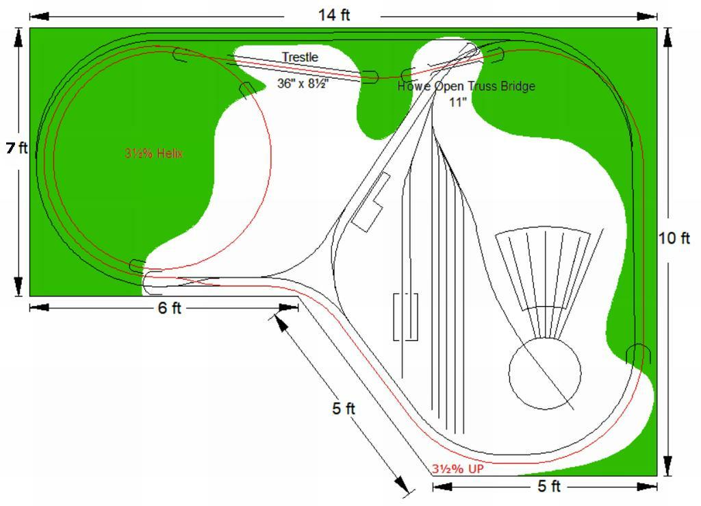
When I designed and built my basic layout (bench work and track) it was for DC in 1988, before DCC for me. It is 10’ x 14’ twice-around 121’ mainline.
There are 14 blocks of approximately 8’ per block. I soldered all the joiners in each block. I have always liked block design since my first layout in 1951.
When I bought my DCC controller in 2005 I rewired my layout to the DCC Guru specs. Biggest mistake of my model railroading career. Without blocks I lost all my block signal detection. Being very disappointed after a couple of months I rewired it back to the original block design.
I was willing to give up on DCC but after the rewiring it to DC the DCC operation worked very good by just connecting the DCC controller to the DC wring, I had my signaling back.
I run dual mode DC or DCC operation, I only have 13 decoders and over 60 locomotives.
I have #19 solid bell wire feeing my blocks, longest run is under 20’ (1½ amps). The max voltage loss to any track is less than .08 volts with two powered locomotives with sound and 13 fully illumined passenger cars. Everything works great.
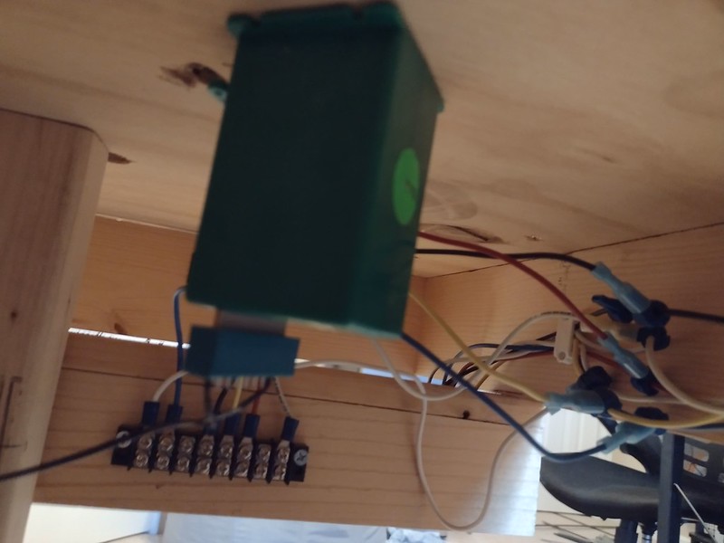
I use EURO connectors for termination of the track wiring at my control panel the other end of the #19 solid wire is soldered to the under side of the rails, 8’ section of track.
There are many many ways to wire your layout and I’m not knocking any of them just saying what works for me. If I had longer block runs I would up the #19 wire to probably #16, which is good for 1½ amps at 30’.
I have terminal strips that connects to my bus using T-Taps to the bus and spade connectors to the terminal strip.
My connections are
+12V (yellow)
+5V (red)
Ground (black)
Rail + (white)
Rail - (blue)
I place a block every 4 feet or so. The spades kind of get in the way of each other, so the best you’ll do is about 6 spades (1 bus tap + 2 hookups on screw 1 and 3 more on screw 2)
I just don’t get why this guy persists in repeatedly making statements that are generally known to be wrong. I cannot even begin to imagine powering my 42’ x 25’ layout with no bus and one pair of feeders from the command station.
I tend to glimpse at his posts just long enough to shake my head and move on. I feel bad for anyone who unwittingly accepts anything he says as true.
The OP asked about terminal strips. Implied was the idea that layout wiring might be complex, justifying use of terminal strips. It is not necessary to use terminal strips. There are some advantages to doing so, depending on a number of factors.
DCC wiring is far simpler than for DC with Block control. In fact you can just connect your layout with just two wires and it should work fine for most home sized layouts.
It’s the rails that conduct power tomeach loconotive anywhere on the layout without interruption. The simplest way to achieve that is to fit your joiners so they conduct electricity reliably and then connect one power wire to each of the two rails at any convenient spot in the layout. I know this works just fine.
Neither bus wires nor multiple feeders are required unless your joiners are no good or you have a very long track and experience significant voltage drop. If and when you do it is a simple matter to add track feeders from rails known to carry good power to the troublesome rails, or add two bus wires if voltage drop is an issue, at any time you feel the need to.
Wiring multiple feeders before you know you need to is not necessary in order to build an operating DCC layout. In fact, adding wiring defeats one of the big advantages of DCC.
I consider a 20’x10 around the room layout to be a large layout.
I’m not sure this ever really got answered in the mess that your thread unfortunately turned into. Ideally, you have the shortest bus runs possible with the shortest feeders possible (within reason). Hard to do placing your DCC system at one “end” of the layout. If I recall, your layout has figure 8 shaped benchwork, yes? To place your DCC booster at a location and run bus wire around the room and across the center of the “8” would likely mean a fairly long bus. Not necessarily unworkable, but could be better. Place your booster along one side of the “8”, lets say the left side, right at the center. Connect your booster to a terminal strip with all the screws on one side connected as has been shown in the thread. Then run a bus from the terminal strip along the top loop of the “8”. Run another bus along the bottom loop of the 8, also connecting it at the terminal strip. Finally, run a third bus across the center of the “8”. Makes for an easy way to connect up a wiring plan like this that minimizes wire run. Obviously you drop your feeders from each section down to the corresponding bus. While you could simply solder all the busses together and eliminate the terminal strips, should a problem arise, and you’ve electrically isolated the various sections of your layout fed by each respective bus, it’s a simple matter of unscrewing and disconnecting a single post on the terminal strip to isolate a part of the layout for troubleshooting purposes.
Solid or stranded? For solid wire, its 12awg. For stranded, it falls between 12awg and 14 awg.
The above post is the most directly relevant post to the OP.
Incidentally, if you do install a two wire bus paralleling your rails it only makes sense to use at least 16 gauge wire, maybe even 14 gauge. To work usefully the bus should be at least as good a conductor as the rails because its only function is to connect power to the rails at points where for some reason the rail joints aren’t enough. The bus is only a back up connection, unless you also need power districts analogous to DC Blocks, i.e. you deliberately interrupt track continuity with insulating gaps. DCC on a home layout makes Blocks unnecessary.
A bus just provides a parallel path for power that only needs to flow though the rails. That’s what a bus does. The question is: is a bus necessary? No it isn’t.
If the power is not flowing all the way through the rails then any continuity gaps are connected through the bus. Belt and suspenders. The question you ask yourself is how likely is it going to be that the rails won’t be enough? Should I assume the worst case and fit a bus right at the start of construction or can I just run additional wires later if and when I need to. For DC Block wiring you don’t have that choice but for DCC wiring you do. Simpler is usually better.
By adding a parallel path for power with bus wires (of any gauge) you can also reduce voltage drop but only if the rails are conducting power also anyway. Voltage drop is not usually a problem for a home sized layout.
It’s a bit more complicated than that. That assumes one long continuous piece of rail. Wouldn’t that be grand?
The point being rail joiners aren’t made of nickel silver don’t conduct high loads perfectly well. Voltage drops occur through thin conductors and changes in material in combination with high current loads.
Now combine this with boosters or track districts, you are asking for damage to your boosters as voltage differences between districts/blocks can easily damage a booster or your locomotives! I had this problem with blown NCE boosters at the club I helped convert to DCC. Minor voltage differences can cause a huge issues.
Feeders are important on Frog rails on turnouts, and every few feet where joint breaks are present. I use 14 gauge bus with 20 gauge feeders under a couple feet long.
For example:
Feed Gauge: 20
Distance: 3 ft
Voltage: 14 volt
Amps: 5
You’ll get a .3V drop on that feeder.
If you have two feeders, that drops to .15V
If you drop it down to 3 amps your voltage drop is .1V with two feeders.
Generally speaking using opto-isolated boosters with < .7V and a 3amp limit breaker should be good enough to prevent most boosters from burning out.
That said
Interestingly enough, Larry posted a video about this topic this very morning.
I should clarify that this is simply size equivalence, not equivalent conductive capability.
Would be useful to have a knowledgeable individual comment on the differences between rail and wire here. There is a reason virtually anything electrical is made from copper and not nickel silver.
An argument could easily be made for a layout in very well climate controlled conditions that busses and feeders are not necessary. However, most if not all modelers don’t have conditions such that prevent expansion and contraction of varying components of a layout. I recall my previous layout, built in a basement, broken into sections or districts for troubleshooting purposes, but only single sets of feeders to each section. Everything ran flawlessly. Until it didn’t. I had very carefully connected each piece of track with TIGHT joiners to ensure continuity with no joints soldered. Over time, expansion and contraction allowed rails to slide ever so slightly back and forth at one specific joint in my yard. The movement resulted in the previously tight rail joiner loosening and failing to conduct power down half the yard (single ended yard, problem joint in the yard ladder). The basement did not have large temperature or humidity swings, but what it did have was enough to cause an issue over time. That’s what modelers who have either been down this road or have listened to other’s war stories are premptively addressing here. Contrary to what one might think, the offending joiner was not an easy find for more reasons t
It’s not just about voltage drop. For example, if you have 2.5Ω resistance between the command station and the farthest point of the layout, a 0.5 amp load will only have a voltage drop of 0.2 volts. That’s probably not noticeable and probably wouldn’t be any issue running trains. The problem is when you have a short, which in this case would draw 4.8 amps. If you have a 5 amp booster, that short wouldn’t shut the booster down and you are a lot more liekly to have something damaged. That’s why the “quarter test” is so often recommended.
Oops, I forgot to mention that I was using 12 volts in my example. Of course, different voltages will have different answers, and using circuit breakers will also. The point is, you can have situations where the voltage drop isn’t a problem but still not have adequate wiring.