Due to space limitations in our new house I am going to build a N scale layout on a door-sized layout made of a slab of two inch pink insulation foam. I want to use block detection senssors to operate a few signals but the current sensing detectors will be on the bottom of the 2 inch thick foam. Will they still operate this far under the track (Kato Unitrack)?
None of what I have read deals with this issue, so I would appreciate any advice you guys could provide.
[#welcome] to the forum, your initial posts are delayed in moderation.
RR_Mel our IR guru needs to comment. He doesn’t limit his placement to underground. https://tinyurl.com/y6mqj5ow
[#oops] you are talking about current sensors. Since I don’t use either, I probably shouldn’t comment at all, but that doesn’t stop other forum members on other subjects.
My understanding is they work by having the feeder wrapped around a sensor on a board. They pretty much have to go under the layout so 2" of foam isn’t going to be a problem.
Current sensors are in the block feeder wires not under the track.
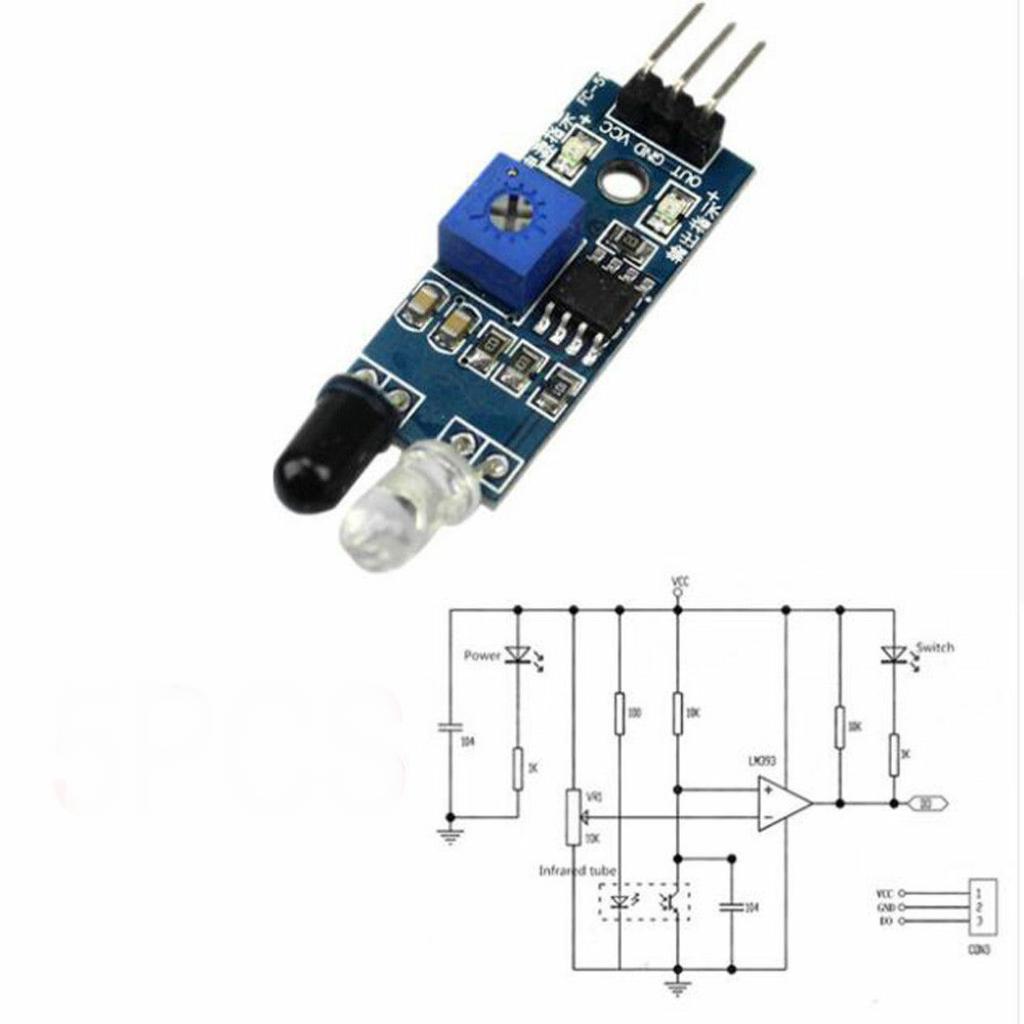
I use reflective type optical IR sensors under the track, above the track and across the track where my track is hidden.
The IR sensor above is a FC-51 sells on eBay for under $1 in bulk.
EDIT:
More info about under the track.
I remove the Sensor and Emitter LED from the FC-51 module and remote them under the track.
I model in HO, easier then N. I made the drilling jig above to drill the holes between the ties. For hidden detecrors I simply bend the sensor and emitter wires 90° toward the rolling stock.
I use NCE BD-20 current detector to operate signals and crossing flashers. There is no distance limit, although the feeder length should be only as long as needed in the case of DCC. The track feeder wire passes through the coil on the sensor between the bus and the rail. They do work well to operate relays to control signals. Mine just hang under the layout held in place by the feeder wire or the DC power wire powering the detector. no adjusting the position for operation.
Just poke a stiff piece of wire down through the foam where you want the detector, then mark the location, drill up through the foam from the bottom, and glue in a plastic tube.
The IR device can then be ‘saboted’ as desired and slid up or down as desired for calibration and then clamped at the bottom.
Use two holes and tubes if your emitter and receiver are both below track and you use ‘bounce’ rather than occlusion to signal occupancy… you can angle the tubes slightly if you want.
I want to use block detection senssors to operate a few signals but the current sensing detectors will be on the bottom of the 2 inch thick foam. Will they still operate this far under the track (Kato Unitrack)?
Thanks
Current sensors are in the block feeder wires not under the track.
I use reflective type optical IR sensors under the track, above the track and across the track where my track is hidden.
The IR sensor above is a FC-51 sells on eBay for under $1 in bulk.
EDIT:
More info about under the track.
I remove the Sensor and Emitter LED from the FC-51 module and remote them under the track.
I model in HO, easier then N. I made the drilling jig above to drill the holes between the ties. For hidden detecrors I simply bend the sensor and emitter wires 90° toward the rolling stock.
The switch and the X thing I refer to are shown on the circuit diagram below the picture of the FC-51 included with you post. The X thing is just to the right of a similar thing identified as, I think, 10X. Possibly they are resistors?
If these are part of the FC-51 I don’t really need to know what they are.
I’ll have to google what an activated switch ground is.
I will try to contact you later this week or next, medical appointments and snow allowing. Are you able to receive PMs? I’m in PA, so there is a several hour difference.
 The IR sensor above is a FC-51 sells on eBay for under $1 in bulk.


