I remember reading in John Armstrong’s “Track Planning for Realistic Operation” about the “Batten Method” to provide transitions to curves to reduce the “Co-efficient of Lurch”. I am planning a small On30 layout that will have some severe elevation changes (In the 4 to 5percent range, but hey, its narrow gauge) Does anyone have a method for transitioning the track/roadbed? I don’t remember reading about it in the book, but I do remember reading somewhere in MR about the need to consider it especially on steeper elevation changes. Thanks for any help you may offer
You willl find other threads about this topic if you search in ‘Search Community’ at right, but you are correct, vertical curves are almost always necessary. The provide surer footing and better adhesion for the engines, but they also prevent some pilots or trip-pins on couplers from snagging on either the rail tops or the ties. For longer steamers with multiple coupled drivers that are not sprung, this becomes very important.
One really good way to achieve this is if you are using 1/2" or similar plywood as your roadbed. We call it cookie cutter roadbed. You firmly anchor the one end with screws and then lift the other end until it can sit atop a riser of wood supported by a frame member or joist. The plywood of quality and durability will form its own vertical curve. It is just that you don’t want to try to force a 3’ length of 1/2" plywood maybe 2" wide up atop a close riser that wants to impart a 15% grade. I know that is ridiculous, but for effect, the idea is to make your transition longer as the grade steepness increases.
You would reverse the anchoring process at the top of the grade to achieve a transition out of the grade, and for all the same reasons.
I hope that helps you.
-Crandell
I make elevation changes on my railroad from 42" (hidden staging) all the way up to 63" in my opinion using traditional cookie cutter method you can accomplish this but with a lot more difficulty then using spline subroadbed method such as I use. If your not familiar with the concept I’ll try and give you a some what condensed examination.My bench work is open grid with 1x4 risers. The splines are cut from 3/4" clear pine shelving.(cheap and easy to work with an flexes extremely well.) You rip the shelving into 1/4" wide strips and cut a series of 3/4" square blocks you drill clearance holes in the centers of the 3/4" square blocks and tack them down to the risers with a finishing nail. Do not hammer the nail home but leave it just loose enough so the block can pivot. With you risers clamped to the open grid bench wok with spring clamps that you bought in the big box store for around $2.00/ea. because you are going to need a whole heap of them and your trusty hot glue gun in hand you glue the spline to the pivot block and hold it in place with a spring clamp. you continue doing this the entire length of the piece of spline moving the risers to create the curve (AND) the elevation your trying to achieve. One you have the spline all glued in place you repeat the process by first gluing 3/4" blocks on either side of the pivot block and and on spots along the spline on opposite side of the spline this will give you a place to glue the next piece of spline first on one side and then on the other. You continue doing this until you have the desired width and and the length of the line you want. You then cut pieces of homasote into 8’ length and as wide as you have determined you will need. (My double track mainline is 4-1/2" wide) you will now need to cut kerf’s or slits in the homasote approx. 1/4" apart approx. 3/4 of the way through the homasote so it wil bend around curves. I have gotten it to bend as sharp as 24" radius curves. If you want to eliminate a big messy step you can buy Homabed already pre-cut and mil
To add some specific numbers to Crandell’s words about forming vertical transitions with cookie-cut plywood:
-
My longest pieces of rolling stock are 250mm long over the coupler faces. I arbitrarily set a mainline transition length of 250mm per 1% of grade change, equally divided between the nominal “level” and the nominal “grade.” A summit where a 2% upgrade becomes a 2% downgrade thus has a meter of vertical transition. “Level” is a pencil line perpendicular to the track.
-
Since my coal-hauling shortline has steeper grades and runs shorter equipment, the ‘arbitrary’ transition length is 200mm/1%. The deciding factor is a pair of old wooden coaches. That route is embargoed to longer mainline cars and locomotives.
The biggest reason for vertical easements is to keep the wheels on the rails (and the flanges between them.) They also tend to make life simpler regarding couplers, especially coupler trip pins.
I have seen one layout that resembled a roller coaster - a logging line operated with geared lokies and short cars. The modeler got away with it by providing nice, rounded vertical transitions.
Chuck (Modeling Central Japan in September, 1964 - with transitions, both vertical and horizontal)
If using plywood or spline to transiyion into the “upeasing” or the “overeasing” make sure that the subroadbed material will start 2 risers before and not break until it can be secured again by additional risers. With cookie cutter plywood there is only one seam in the subroadbed and you need to stabilize the forces of the bend. This will ensure that over time it will remain. With spline you have the ability to stager the joints as you ply the spline subroadbed and it isnot as critical. In my opinion, pine or masonite spline is the most stable for subroadbed.
My club uses a combination of cookiecutter 3/4" ply and pine spline for the entire layout. We end up with some excellent very stable trackwork.
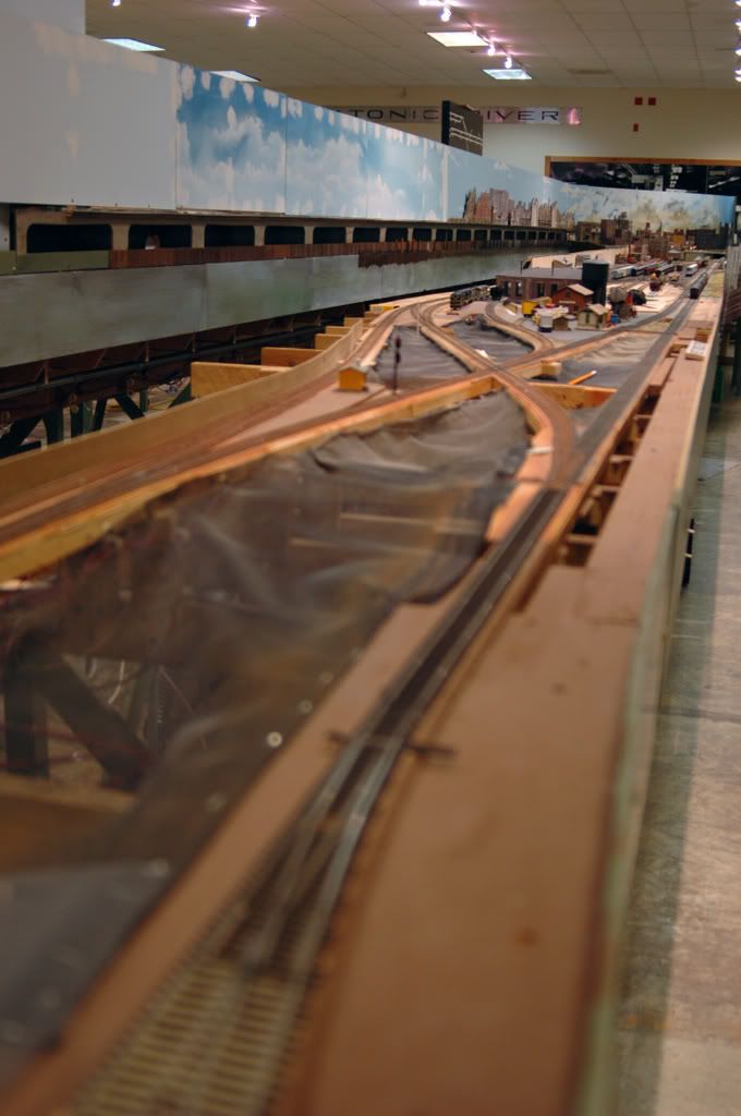
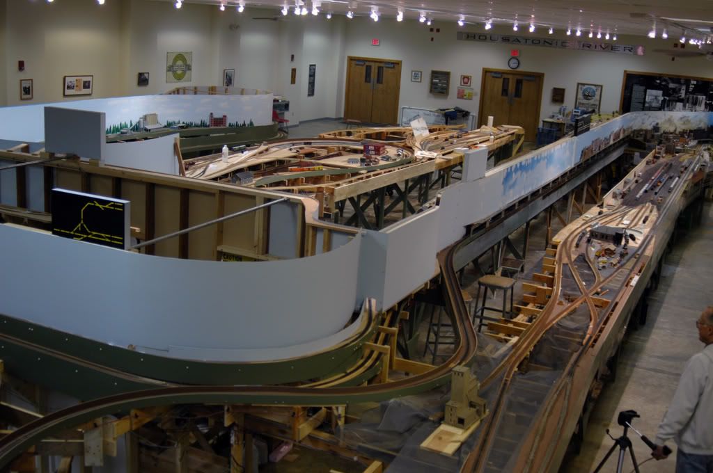
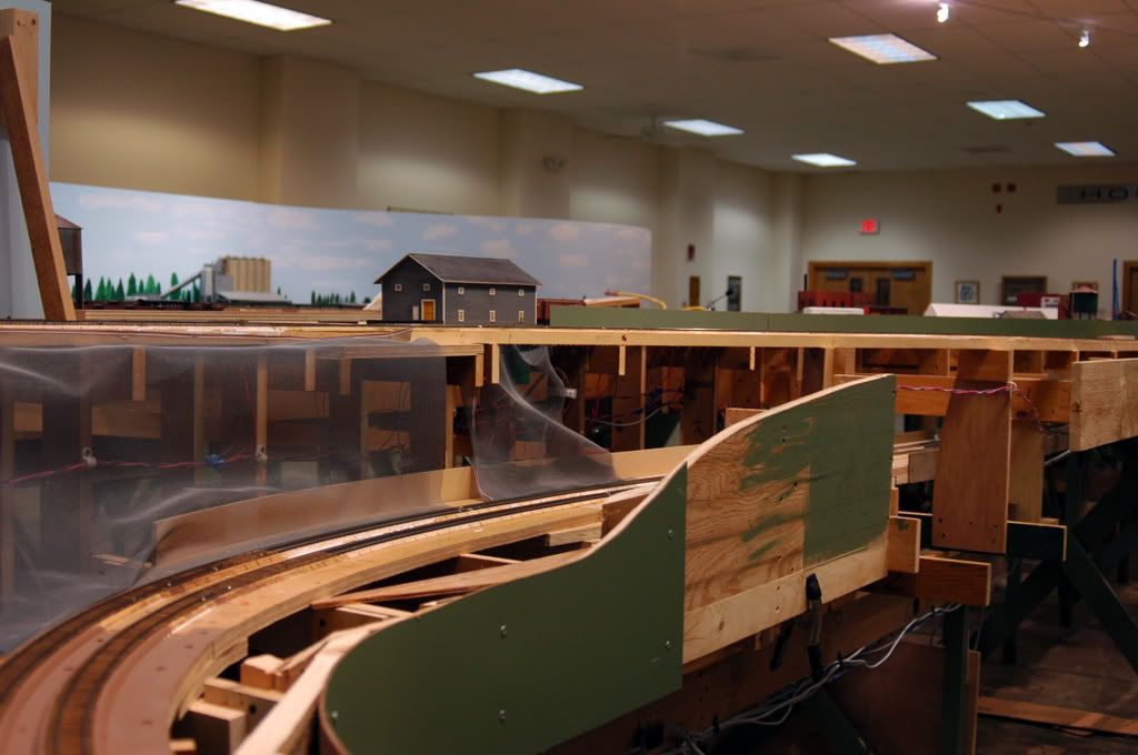
And it’s cheap too!, Bob now that is one heck of a train room and it ain’t even below ground … very nice railroad
Coming up with some kind of computation for vertical easements has been discussed in the Layout Construction and LDSIG Yahoo Groups on several occasions. But nobody has been willing to conduct the research necessary to validate existing rules of thumbs or establish minimums. And so the issue sits.
The prototype generally uses (but not always) parabolic vertical transitions, and cubic spiral horizontal transitions.
There was a set of calculations (I forget by who to give proper credit) that looked at using portions of circular curves for an easement, and then looked at wheel flanges on long rigid frames of steam locomotives. IIRC, a 14ft radius vertical curve would keep half the flange height below the rail head top for even a 4-12-2. This made for a very short transition, as the chord length of 14ft radius to join a difference of 2% grades is less than 10".
And those who use splines or cut 1/2" or thicker plywood for a subroadbed, as mentioned in other posts, have always had sufficient vertical easement due to the stiffness of the materials used, no calculations or trials needed.
I myself am experimenting with 2x longest car length (50ft passenger car in HOn3) vertical transitions to go from 0% to a 6% grade (with both N and HOn3 couplers), but even if successful that will be only 2 data points. Long rigid wheelbases are one issue, but I suspect coupler over/under ride may be even more of a factor. And the closer to scale size the coupler heads, the more likely couplers are to be the driver of the vertical transition.
my thoughts, your choices
Fred W
Thanks for all the responses. So if I really understand all that has been said, If I use 1/2" plywood roadbed and make sure I am straight thru any joints in my roadbed, I probably can not bend it too tight (assuming I don’t break the plys), and if I choose to use a spline system, with staggered joints, the same would be true.
Thanks,
Kevin
I am not sure I understand you above, but if I do, I would not consider having a spliced joint, in either type of roadbed, partway through the vertical curve. The glue would rigidify the joint and about 1" on either side of it sufficiently that you would get a kink in two places with a planar length between them partway along the transition. So, yes, you can splice, but not along the vertical curve. Make your splice at some point between the two transitions or outside of them. Let the natural grains or construction of the material (I used 1/4" MDF for splines, 6 ply) take the loads as it comes on and then abates for the transition.
-Crandell
Crandell
I have had occasion to make bend with a splice some where in the curve but never at the apex of the curve if at all possible. What we did was laminate the two piece of spline together on the floor and wet the entire length after the glue had dried over night. In this instance we chose not to use the hot glue gun. We were planning to build a bending jig that consisted of several saw horses with risers and pivot block clamped in placed at the correct configuration. Having an old accomplished customer furniture maker in the club he suggested wetting the splines to make them more pliable so we tried it on the center spline and it bent very easily without the use of the jig. Tow of use piked up the next 16’ section of spline and tried bending it without wetting it and it bent perfectly although we were holding out breath the entire time. When your using extremely long pieces laminated together the curve is very mild and does not put a great deal of stress on the splice. We reinforce or splice with a thinner spline on either side of the splice giving it added strength and being thinner more bend-ability if thats even a word.
When your talking large radius curves yes it can be done but only if you have no other choice but when it comes to smaller radius curves like is sounds that the O/P will be using no way, you will hear the proverbial snap! a sound I became all to accustomed to until I learned the limitations of spline sub roadbed.
I am happy to read that your experiment worked! I can see that softening the glue a bit might make the difference, although I would be leery of the splines delaminating. I guess you could always clamp the spliced area a bit and try that.
-Crandell
" although I would be leery of the splines delaminating"
Ah the secrete is don’t use laminated wood. I use only the best grade clear pine shelving, no knots and real wood, the pine is soft so it bends nicely. Soaking the wood is an old furniture makers trick I have seen trim carpenters use it too. I have also seen a steam box used to make permanent bows in wood but something tells me they don’t make steam boxes that big…lol
You need to take a look at wooden boat building. Steam boxes are/were built to need, often on the spot, to steam bend large pieces of oak and other hard woods to the required shape. The world-venturing wooden ship navies of the 17th through 19th Centuries carried shipwrights who rebuilt natural and battle damage anywhere in the world from standing trees. This would include locally built steam boxes on the beach.
I’ve never seen it, but I’m sure 19th Century coopering required some steaming to build the common wood barrels used to store and transport most anything.
Steaming wood, like small time metal machining, were once common skills that have become rarely practiced arts in our day.
Fred W
Model Railroader Magazine, March 1979, page 147.