I would like to have at least one crossing on my layout with working lights. This item says specifically not for DCC layouts. I don’t understand why. It draws power from the track but why couldn’t that source be an aux power supply and not the DCC source? What am I missing here?
That’s what I was thinking. None of the sensors or signals have any connection to the track or DCC power. The power feeds for the controller could be from my accessory power bus the way I see it.
I don’t use the Walthers controller but I seem to recall that the track power is what told the sensors what the direction of travel was by detecting the rail polarity, something DCC will not provide.
Since each crossing approach has a pair of sensors (presumably to ascertain direction of travel), I don’t see why rail polarity would matter. That connection to the rails is a mystery.
I agree. That’s what’s puzzling me. I don’t see the necessity for track connections. It seems, to me, the connections to their POWER PACK should be all that’s required. The sensors are independent of the track and the controller gets power from the POWER PACK so why would it not work with DCC? No track polarity involved.
I know this is not an answer for the original poster, but this is what I did.
I bought a $3 nano board, four 30 cent light sensors, and after watching a Youtube video, wrote a simple Arduino program that activates and blinks the lights for a double mainline.
I’m in my 70s and fairly dumb, so if I can do it, anyone can.
The only thing I’m going to change is substitute infrared sensors for the light sensors. It was a pain adjusting the program so the light sensors would work in certain room lights.
As I see it the main problem is that DC has a different polarity depending on the direction of approach. DCC has a fixed polarity. This must have some effect on the way the controller treats the approach and departure sensor signals.
I thought these systems worked by gauging both direction and speed by measuring the extinction times of the pairs of photodetectors. The polarity or even the presence of voltage on the rails at all should have nothing to do with operation.
I think the ‘argument’ is whether DCC track power with Lenz modulation (imposed square wave with reversing base DC polarity) is suitable to run a device built for rectified/smoothed DC input.
I find it amusing that this thread continues despite the fact that Walthers, the manufacturer, cautions that use if the controller on a DCC powered layout can damage the device.
Well, I don’t know if “argument” is the right word for my question or not.
The power source is an external power pack.
The photo sensors are powered by that.
The sensors work based on position inside the rails and don’t have anything to do with polarity.
SO…
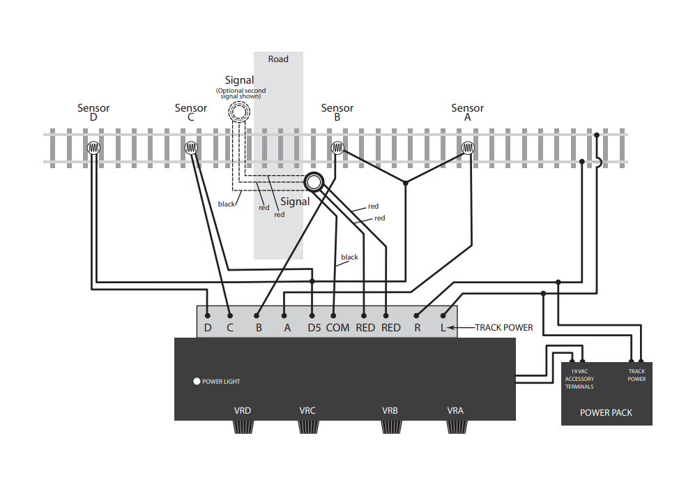
WHY DOES IT HAVE THE 2 WIRES GOING TO THE RAILS THEN?
Just a confusing bit of wiring to me. What is their purpose?
The 2 wires would not go to the rails on a DCC layout; if you look at the diagram it indicates you’re taking ‘DC track power’ from a DC power pack or equivalent; taking it from ‘the rails’ is probably to shorten the wiring distance to wherever the controller is installed on the layout, close to the crossing. On a DC layout.
I note that the installation in the video is for a ‘DCC/DC’ layout. This obviously won’t have connections to the rails themselves even if part of the time the layout is operating in DC. And indeed he’s got some kind of connection to “an old Tyco power pack” that goes through some weird ‘loopback’ connection he doesn’t explain and then to a 19VAC connection … someone needs to explain what that’s doing, as I can’t.
I was wrong about how the sensors work. They work in pairs: the further away turns the flashers on (and disables the nearer sensor on that side), then the sensor immediately across the crossing turns the activation off.